Table of Contents
Advertisement
Quick Links
Advertisement
Table of Contents

Related Manuals for Inverter Pulsar


Summary of Contents for Inverter Pulsar
- Page 1 Installation and operation instructions Pulsar Extractor fan www.inventer.eu...
- Page 2 The illustrations in this documentation may differ slightly from the design of the product that you have purchased. The same functionality is ensured despite any design deviations. Pulsar extractor fan | Installation and operation instructions...
-
Page 3: Table Of Contents
PIN-code/serial number ........... 28 5.1 Fit the wall sleeve and route cables ....14 5.2 Mount power supply unit (optional) ....15 5.3 Insert and connect the Pulsar ......16 6 Commisioning ............21 Pulsar extractor fan | Installation and operation instructions... -
Page 4: User- Und Safety Instructions
Non-observance of safety instructions could result in injury NOTICE means: Direct or possible risk of property and/or property damage. damage due to an adverse event/state. Pulsar extractor fan | Installation and operation instructions... - Page 5 ( Chapter 3.1, Page 8). taking into account the technical data and applications - Do not use the Pulsar in places where direct contact with described in this manual, and only in conjunction with the splashing water is possible over a long period of time...
-
Page 6: System Overview
Qualified personnel Installation is possible in ceilings and exterior walls. If the Pulsar extractor fan is used as an overflow fan, it can also Installation and electrical connection of the unit may only be installed in interior walls. The Pulsar allows connection... -
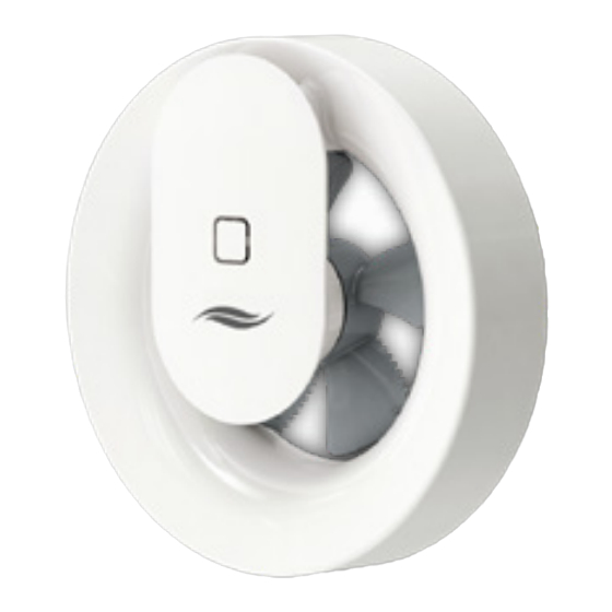
Page 7: Function
SYSTEM OVERVIEW If required, the Pulsar can also be used as an overflow 1 Rubber seal fan for ventilating and heating neighbouring rooms without 2 Fan housing heating facilities. The Pulsar switches on when the selec- 3 Fan ted temperature limit is exceeded. It switches off again... -
Page 8: Preparing For Installation
Electrical protection areas according to 0100 Positioning of the Pulsar DANGER • Install the Pulsar extractor fan in the room´s air flow to Infiltration of water into the Pulsar extractor fan ensure optimum moisture removal and reliable readings or its power source. -
Page 9: Dimensions
GmbH Electrical connection The Pulsar extractor fan can be connected directly to the AC 230 V mains or operated safely with extra-low voltage 12 V DC (SELV). A power supply unit (PSU) is optionally available. -
Page 10: Electrical Connection Ac 230 V
AC 230 V Sensor-controlled, without continuous ventilation: • Factory setting (on-demand controlled ventilation). • The Pulsar switches on and off automatically when acti- DC 12 V vated by the integrated humidity or light sensor. Figure 5: Pulsar 230 V AC with active sensors... -
Page 11: Electrical Connection Dc 12 V
Use as an overflow fan: • Setting must be selected via the inVENTer Mobile App. • Suitable for ventilation of adjacent rooms. • The Pulsar is switched on and off based on temperature; AC 230 V the light and humidity sensors are inactive. - Page 12 The connection of the exhaust fan depends on the desired functions. Make sure to connect the exhaust air fan correctly and select the correct presettings for your functions during commissioning.The switch S1 integrated on the exhaust fan Pulsar has no function when connecting 12 V DC. Sensor controlled functions...
- Page 13 AC 230 V AC 230 V DC 12 V Figure 10: Wiring diagram for NT16 flush-mounted power supply unit and Pulsar extractor fan 12 V DC (sensor-cont- rolled and use as overflow fan) Usage as overflow fan: • Setting must be selected via the inVENTer Mobile •...
-
Page 14: Installation
• Mount Pulsar extractor fan outside the protection area 0 according to VDE 0100. • Only install the Pulsar in areas of protection zone 1 where direct contact with splash water is not possible over a longer period of time and/or the unit is not exposed to direct jets of water. -
Page 15: Mount Power Supply Unit (Optional)
► Install the mounting box on the inside wall. The aV100 wall mounting set (wall sleeve incl. non-return valve and external termination), which serves as a receptacle for the Pulsar extractor fan, and is optionally available from inVENTer GmbH. Routing cables ►... -
Page 16: Insert And Connect The Pulsar
► Use a screwdriver to press in the lock button (red Hold the fan unit firmly so that it does not fall to arrow) on the fan casing. the floor when it is removed. ► Loosen the cover of the fan housing. Pulsar extractor fan | Installation and operation instructions... - Page 17 5 cable inlets with the aid of Starting on the side of the integrated switch a suitable tool. pressing down on the opposite side. Place the cable gland near the respective terminal. Pulsar extractor fan | Installation and operation instructions...
- Page 18 The lettering TOP is legible and facing upwards. ► Screw the base plate of the fan housing to the inside wall. The rubber seal completely seals the extractor fan to the inner wall. Pulsar extractor fan | Installation and operation instructions...
- Page 19 ► Attach the shortened connection cable, according to the connection diagram, in the connection terminal of the base plate. 4: Terminal assignment, connection diagrams. The Pulsar extractor fan is inserted and connected. Pulsar extractor fan | Installation and operation instructions...
- Page 20 inserted. • AC 230 V: Switch on the Pulsar. The switch is loca- ted on the left side of the housing. Push it upwards to position 1. Pulsar extractor fan | Installation and operation instructions...
-
Page 21: Commisioning
Direct pairing via Bluetooth LE will lead to installation errors and the Pulsar must be reset. Depending on the electrical connection of the Pulsar, different functions and settings are available within the app. Requirements for the functionality of the app: •... -
Page 22: Operation
Mobile offers and can download the app directly: • Boost function • Intelligent pause function: 1 time per day you can run your Pulsar for a freely selected period of time either OFF (only possible if no continuous ventilation is set) or at minimum power (continuous ventilation). -
Page 23: Led-Display
The blue or white LED must light up when you want malfunction of the ventilation system! to operate or configure the Pulsar extractor fan. • Do not allow all cleaning and maintenance of the ventilation system to be carried out by children... - Page 24 ► Disconnect the power supply. • AC 230 V: Disconnect the connection at the switch of the Pulsar. The switch is located on the left side of the fan housing. Push it down to the 0 position. • DC 12 V: Interrupt the power supply at the mains fuse or at the external switch.
-
Page 25: Technical Data
Ambient temperature [°C] 5 – 50 Without Supply air aggressive gases, dusts and oils Diameter x Depth [mm] 177 x 81 Air flow characteristic curve Pulsar Luftvolumenstrom (m³/h) Air volume flow [m³/h] Pulsar extractor fan | Installation and operation instructions... -
Page 26: Scope Of Supply
The disassembly necessary for disposal is carried out in Technical customer service reverse assembly order. For technical advice, please contact our technical service staff. +49 (0) 36427 211-0 info@inventer.de +49 (0) 36427 211-13 www.inventer.eu Pulsar extractor fan | Installation and operation instructions... -
Page 27: Warranty Und Guarantee
Failure to observe the intended use will invalidate all warranty claims. Manufacturer guarantee inVENTer GmbH provides a five-year warranty on the Pulsar extractor fan. This covers premature product wear. Information on the warranty conditions can be found at www.inventer.eu/guarantee. Warranty and guarantee claims In the event of a warranty or guarantee claim, contact the distributor or factory representative responsible for you. -
Page 28: Pin-Code/Serial Number
PIN code / serial number Important! To activate the inVENTer Mobile app, enter the PIN code or scan it with your phone. You can also find your specific PIN code on the right foot of the fan unit. inVENTer GmbH Ortsstraße 4a D-07751 Löberschütz www.inventer.eu...
Need help?
Do you have a question about the Pulsar and is the answer not in the manual?
Questions and answers