
Related Manuals for Inverter iV-Office


Summary of Contents for Inverter iV-Office
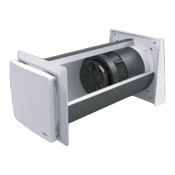
- Page 1 Installation instructions iV-Office Ventilation device with heat recovery www.inventer.eu...
- Page 2 GmbH Phone: +49 (0) 36427 211-0 Ortsstraße 4a Fax: +49 (0) 36427 211-113 D-07751 Löberschütz E-mail: info@inventer.de Germany Web: www.inventer.eu CEO: Annett Wettig VAT ID number: DE 815494982 Jena District Court HRB 510380 iV-Office ventilation device | Installation instructions...
-
Page 3: Table Of Contents
Installing the inner cover panel ..................34 Technical data .......................... 35 General specifications ....................35 iV-Office energy label according to ErP Directive, Regulation 1254/2014 ..... 36 Specifications according to ErP Directive, Regulation 1254/2014 ......... 37 Scope of supply ........................39 Troubleshooting ........................ -
Page 4: User And Safety Instructions
Action required: This prompts the user to perform a specific action. ► Check the results requires you to check the results of the action you have performed. Action focus: To be taken into account in the corresponding assembly step. iV-Office ventilation device | Installation instructions... -
Page 5: Safety Instructions
Non-observance of safety instructions could result in injury and/or property damage. These installation instructions only cover the standard variant (referred to as the "Standard variant" in the following text) of the iV-Office ventilation device. Information on the variants can be found in the separate installation instructions for the respective components. - Page 6 You should connect all controllers via a mains fuse in the house distribution board. If your device has a fault, contact your nearest distributor or our technical service. Any kind of use other than the intended use will exclude all liability claims. iV-Office ventilation device | Installation instructions...
- Page 7 The ventilation device complies with the technical safety requirements and standards of electrical appliances for domestic use. It conforms to current European Union and United Kingdom directives. The full text of the EU declaration of conformity is available at the following Internet address: https://www.inventer.eu/downloads/ . iV-Office ventilation device | Installation instructions...
-
Page 8: System Overview: Iv-Office Ventilation Device
The ventilation device consists of a wall sleeve in which the thermal accumulator insert is mount- ed. A lockable inner cover conceals the iV-Office discreetly from the interior. The filter integrated into the inner cover ensures that no pollen or dust from outside enters the interior. Outside, a driving rain-proof cover conceals the components of the ventilation device. -
Page 9: Construction
SYSTEM OVERVIEW: IV-OFFICE VENTILATION DEVICE Construction Standard variant Flex Office Figure 1: Overview of the iV-Office ventilation device Components External termination: Thermal accumulator insert Flex Office weather protection hood (Thermal accumulator, inVENTron, sound insulation lining made of Inventin) 1 Weather protection hood base plate... -
Page 10: Function
The most important components of the iV system are the ceramic thermal accumulator, the reversing fan, air guiding vanes for straightening the air volume flow, filters for different hygienic requirements, a closable inner cover and an outer cover. A control device (controller) completes the system. iV-Office ventilation device | Installation instructions... - Page 11 SYSTEM OVERVIEW: IV-OFFICE VENTILATION DEVICE Ventilation device iV-Office with heat recovery The iV-Office ventilation system is used to provide ventilation for living spaces and living space-like commercial premises. The combination of inVENTron, thermal accumulator and sound insulation lining ensures maximum heat recovery with minimum sound emissions and maximum air flow.
-
Page 12: Control Elements
Cable Cable External interface 1 potential-free switching 1 potential-free switching con- contact per Control module: tact per controller: Pressure switch (NC) Pressure switch (NC) • • Other sensors (NO) Other sensors (NO) • • iV-Office ventilation device | Installation instructions... - Page 13 Device communication Cable External interface 1 potential-free switching contact per Clust-Air module (max. 4) Pressure switch (NC/NO) • Other sensors (NO) • For detailed information, see the controller's installation and operating instructions. iV-Office ventilation device | Installation instructions...
-
Page 14: Preparing For Installation
1,2 m – 0,75 y 1,2 m 1,2 m Installation over corner 1,0 m 1,0 m 1,4 m 1,0 m 1,0 m 1,4 m 1,2 m – 0,75 y 1,2 m – 0,75 y iV-Office ventilation device | Installation instructions... -
Page 15: Position Of The Wall Opening
≥ 250 Ø Position of wall opening Position of Simplex wall sleeve system Figure 2: Dimensional drawing of the iV-Office wall opening (interior view) 1 Wall opening (Fig. 2, left) 3 Reveal Simplex wall installation system (Fig. 2, right) 4 Door/window frame... -
Page 16: Sectional Drawing Of The Ventilation Device
Sectional drawing of the ventilation device For sectional drawings of other variants of your ventilation device, see the installation instructions for your specific external termination. Sectional drawing of the iV-Office ventilation device, standard variant 1 – 2° Wandstärke ≥ 260... -
Page 17: Dimensional Drawings Of Components
Figure 5: Dimensional drawing of the Flair XL V-280x280 inner cover incl. SDE 1 Inner cover panel 5 Interior wall fixing borehole 2 SDE sound insulation insert 6 Inner cover base plate 3 Flair XL adapter 7 Pass-through for controller connecting 4 Spacer (4 x) cable iV-Office ventilation device | Installation instructions... -
Page 18: Installation And Assembly
4 Innenblende Flair XL 4 a: Flair XL insert (pre-installed) 4 b: Inner cover base plate 4 c: ISO Coarse 60 % filter 4 d: Interior wall fixing material WSH = Weather proteccion hood iV-Office ventilation device | Installation instructions... -
Page 19: Create Wall Opening
The wall sleeve must have a slope of 1 – 2° to the exterior wall side. Alternatively the drilling can be carried through with a slope. The wall opening for the ventilation device has been created. iV-Office ventilation device | Installation instructions... -
Page 20: Laying The Cables To The Wall Opening Of The Ventilation Device
Pure Operating voltage fan Stranded cable Pure controller module and device 6 – 16 V DC, sMove sMove operating device communication e. g.: LiYY 3x0.75 mm² MZ-Home Clust-Air module CAM17 in the ventilation zone iV-Office ventilation device | Installation instructions... - Page 21 Cable type LiYY, 3-wire, Star-shaped: Ventilation wire cross-section 0.75 mm², length max. 33 m devices Operated in pairs Control device: Terminal Switching power Pure: Control module blocks supply device sMove: Control device MZ-Home: Clust-Air module iV-Office ventilation device | Installation instructions...
-
Page 22: Installing The Wall Sleeve
The recess for the connecting cables is located on the interior wall side and near the cables laid to the wall opening. ► Guide all connecting cables through the cut-out in the wall sleeve. iV-Office ventilation device | Installation instructions... - Page 23 Take care not to damage the connecting cable on the interior wall. ► If necessary, trim the wall sleeve so it is flush with the render. ► Deburr the edges. The wall sleeve is installed. iV-Office ventilation device | Installation instructions...
-
Page 24: Installing The Ventilation Device's External Termination
► Level the base plate using a spirit level. ► Mark the four drill holes (blue arrow). ø 8 mm ► Drill the four holes with Ø 8 mm, min. 50 mm deep. iV-Office ventilation device | Installation instructions... - Page 25 ► Place the cover onto the base plate from the top. ► Slide the cover downwards as far as the stop. The guides on the cover hook in behind the base plate. The Flex Office weather protection hood is installed. iV-Office ventilation device | Installation instructions...
-
Page 26: Inserting The Thermal Accumulator Insert
Position the abutting surfaces (red arrow) in the upper section of the wall sleeve (approx. 12 o'clock). ► Make sure that the sound insulation lining made of Inventin is pushed into the ring insert on the weather protection hood. iV-Office ventilation device | Installation instructions... - Page 27 ► Shorten the sound insulation lining on the inner wall side with a cutter so it is flush with the wall sleeve. Do not damage the connecting cable on the interior wall. The sound insulation lining is inserted. iV-Office ventilation device | Installation instructions...
- Page 28 ► Insert the inVENTron from the interior into the wall sleeve so that you can reach the BUS plug connection. The narrow Slim guiding vane [16 mm] is aligned towards the interior. Slim The thermal accumulator insert has been inserted. iV-Office ventilation device | Installation instructions...
-
Page 29: Installing The Inner Cover Base Plate
► Clip the adapter into the base plate so that • The position arrow on the base plate is pointing upwards, and • The positions of the cable entry and connecting cable match. The inner cover base plate is prepared. iV-Office ventilation device | Installation instructions... - Page 30 ► Screw the base plate into the rawl plugs with the screws. The position arrow on the base plate points upwards. The inner cover base plate is fitted. iV-Office ventilation device | Installation instructions...
-
Page 31: Electrical Connection Of The Reversible Fan
INSTALLATION AND ASSEMBLY Electrical connection of the reversible fan The function of the iV-Office ventilation system requires the simultaneous operation of two iV-Office ventilation devices in push-pull mode. This section therefore describes the connection of a pair of devices, not a single device. - Page 32 5 Clamping screws on the controller 2 Plug-in connector on the fan cable plug-in connector 3 Plug-in connector on the controller cable 6 Clamping screws on the fan plug-in 4 Fan BUS [to controller] connector iV-Office ventilation device | Installation instructions...
-
Page 33: Check Function And Complete Fan Installation
► Make sure that all reversible fans rotate in the direction appropriate to their connections. Start direction extract air mode: Start direction supply air mode: Direction of fan clockwise Direction of fan counter clockwise inVENTron is connected and installed. iV-Office ventilation device | Installation instructions... -
Page 34: 4.10 Installing The Inner Cover Panel
4 x CLICK ► Press the locking lugs inwards on the spacers. ► Slide the inner cover panel onto the spacers. All spacers noticeably snap in. The inner cover panel is fitted. iV-Office ventilation device | Installation instructions... -
Page 35: Technical Data
Sensitivity of the air flow at ± 20 Pa (EN 13141-8) Electrical protection area Outside protection areas 0 – 2 (in accordance with VDE 0100) Automatic by reversing operation Frost protection (down to -20 °C) Conformity iV-Office ventilation device | Installation instructions... -
Page 36: Iv-Office Energy Label According To Erp Directive, Regulation 1254/2014
TECHNICAL DATA iV-Office energy label according to ErP Directive, Regulation 1254/2014 On the energy label you will find the following information from the product data sheet: • Energy efficiency class (SEC class) • Sound power level L • Maximum air flow (supply air) -
Page 37: Specifications According To Erp Directive, Regulation 1254/2014
TECHNICAL DATA Specifications according to ErP Directive, Regulation 1254/2014 iV-Office ventilation device, demand-controlled: iV-Office product data sheet according to EU Ordinance 1254/2014 dated 11 July 2014 Description Values Supplier inVENTer GmbH Model identifier iV-Office Cold -88.481 SEC class / Specific Energy Average -44.234... - Page 38 TECHNICAL DATA iV-Office ventilation device, manually controlled: iV-Office product data sheet according to EU Ordinance 1254/2014 dated 11 July 2014 Description Values Supplier inVENTer GmbH Model identifier iV-Office Cold -82.817 SEC class / Specific Energy Con- Average -39.977 sumption (SEC) [kWh/(m²a)] Warm -15.435...
-
Page 39: Scope Of Supply
Wall sleeve with styrofoam discs and mounting wedges Wall sleeve R-D250x495 1506-0072 Wall sleeve R-D250x745 1506-0073 Thermal accumulator insert iV-Office thermal accumulator insert [incl. Inventin 495 mm] 1507-0028 iV-Office thermal accumulator insert [incl. Inventin 745 mm] 1507-0029 Inner cover Flair XL V-280x280 inner cover, white, incl. SDE... -
Page 40: Troubleshooting
Check the connector plug on the control- Supply air is cold ler. The connector plug must be sitting firmly in the connector housing. The controller is operating in Select heat recovery mode on the ventilation mode. controller. iV-Office ventilation device | Installation instructions... -
Page 41: Warranty And Guarantee
To order components for your ventilation device, contact your nearest distributor or our service staff. Technical customer service For technical support contact our service staff: +49 (0) 36427 211-0 +49 (0) 36427 211-113 info@inventer.de http://www.inventer.eu iV-Office ventilation device | Installation instructions... - Page 42 inVENTer GmbH Ortsstraße 4a D-07751 Löberschütz Germany www.inventer.eu Subject to modifications. We accept no liability for printing errors. Item number: 5001-0043 Version: 2.0 – 06/2022...
Need help?
Do you have a question about the iV-Office and is the answer not in the manual?
Questions and answers