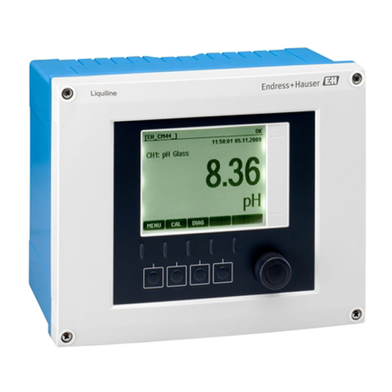
Endress+Hauser Liquiline CM442 Brief Operating Instructions
Universal four-wire multichannel controller
Hide thumbs
Also See for Liquiline CM442:
- Operating instructions manual (178 pages) ,
- Brief operating instructions (40 pages) ,
- Operating instructions manual (170 pages)
Table of Contents
Advertisement
Quick Links
KA01159C/07/EN/07.21
71525975
2021-03-24
Products
Brief Operating Instructions
Liquiline
CM442/CM444/CM448
Universal four-wire multichannel controller
These instructions are Brief Operating Instructions; they are
not a substitute for the Operating Instructions pertaining to
the device.
Detailed information on the device can be found in the
Operating Instructions and in the other documentation
available at:
• www.endress.com/device-viewer
• Smart phone/tablet: Endress+Hauser Operations App
Solutions
Services
Advertisement
Table of Contents

Subscribe to Our Youtube Channel
Related Manuals for Endress+Hauser Liquiline CM442


Summary of Contents for Endress+Hauser Liquiline CM442
- Page 1 These instructions are Brief Operating Instructions; they are not a substitute for the Operating Instructions pertaining to the device. Detailed information on the device can be found in the Operating Instructions and in the other documentation available at: • www.endress.com/device-viewer • Smart phone/tablet: Endress+Hauser Operations App...
- Page 2 Liquiline CM442/CM444/CM448 Order code: XXXXX-XXXXXX Ser. no.: XXXXXXXXXXXX Ext. ord. cd.: XXX.XXXX.XX Serial number www.endress.com/deviceviewer Endress+Hauser Operations App A0040778 Endress+Hauser...
-
Page 3: Table Of Contents
Liquiline CM442/CM444/CM448 Table of contents Table of contents About this document ............. . 4 Warnings . -
Page 4: About This Document
About this document Liquiline CM442/CM444/CM448 About this document Warnings Structure of information Meaning This symbol alerts you to a dangerous situation. DANGER Failure to avoid the dangerous situation will result in a fatal or serious injury. Causes (/consequences) If necessary, Consequences of non- compliance (if applicable) ‣... -
Page 5: Symbols On The Device
Liquiline CM442/CM444/CM448 About this document Symbols on the device Symbol Meaning Reference to device documentation Documentation The following instructions complement these Brief Operating Instructions and are available on the product pages on the Internet: • Operating Instructions Liquiline CM44x, BA00444C •... -
Page 6: Basic Safety Instructions
Basic safety instructions Liquiline CM442/CM444/CM448 Basic safety instructions Requirements for personnel • Installation, commissioning, operation and maintenance of the measuring system may be carried out only by specially trained technical personnel. • The technical personnel must be authorized by the plant operator to carry out the specified activities. -
Page 7: Workplace Safety
Liquiline CM442/CM444/CM448 Basic safety instructions Workplace safety As the user, you are responsible for complying with the following safety conditions: • Installation guidelines • Local standards and regulations • Regulations for explosion protection Electromagnetic compatibility • The product has been tested for electromagnetic compatibility in accordance with the applicable international standards for industrial applications. - Page 8 Basic safety instructions Liquiline CM442/CM444/CM448 IT security measures in line with operators' security standards and designed to provide additional protection for the device and device data transfer must be implemented by the operators themselves. Endress+Hauser...
-
Page 9: Incoming Acceptance And Product Identification
Liquiline CM442/CM444/CM448 Incoming acceptance and product identification Incoming acceptance and product identification Incoming acceptance Verify that the packaging is undamaged. Notify the supplier of any damage to the packaging. Keep the damaged packaging until the issue has been resolved. -
Page 10: Scope Of Delivery
A new window (Device Viewer) opens. All of the information relating to your device is displayed in this window as well as the product documentation. 3.2.3 Manufacturer address Endress+Hauser Conducta GmbH+Co. KG Dieselstraße 24 D-70839 Gerlingen Scope of delivery The scope of delivery comprises: •... -
Page 11: Installation
Liquiline CM442/CM444/CM448 Installation Installation Mounting conditions 4.1.1 Mounting plate 4 x 6.5 (0.26) 80 (3.15) 125 (4.92) A0012426 1 Mounting plate, dimensions in mm (in) Endress+Hauser... -
Page 12: Mounting The Measuring Device
Installation Liquiline CM442/CM444/CM448 4.1.2 Weather protection cover NOTICE Effect of climatic conditions (rain, snow, direct sunlight etc.) Impaired operation to complete transmitter failure are possible! ‣ Always use the weather protection cover (accessory) when installing the device outdoors. 300 (11.8) 170 (6.69) - Page 13 Liquiline CM442/CM444/CM448 Installation A0033044 3 Post mounting Weather protection cover (optional) Spring washers and nuts (post mounting kit) Post mounting plate (post mounting kit) Pipe or railing (circular/square) Spring washers and nuts (post mounting kit) Mounting plate Pipe clamps (post mounting kit)
- Page 14 Installation Liquiline CM442/CM444/CM448 4.2.2 Rail mounting A0012668 6 Rail mounting Weather protection cover (optional) Pipe or railing (circular/square) Post mounting plate (post mounting kit) Mounting plate Spring washers and nuts (post mounting kit) Threaded rods (post mounting kit) Pipe clamps (post mounting kit)
-
Page 15: Post-Installation Check
Liquiline CM442/CM444/CM448 Installation 4.2.3 Wall mounting ≥ 340 (13.4) A0027798 10 Wall mounting A0012686 Wall 9 Installation clearance in mm (in) 4 drill holes Mounting plate Screws Ø 6 mm (not part of scope of supply) The size of the drill holes depends on the wall plugs used. The wall plugs and screws must be provided by the customer. -
Page 16: Electrical Connection
Electrical connection Liquiline CM442/CM444/CM448 Electrical connection Connecting the measuring device WARNING Device is live! Incorrect connection may result in injury or death! ‣ The electrical connection may be performed only by an electrical technician. ‣ The electrical technician must have read and understood these Operating Instructions and must follow the instructions contained therein. - Page 17 Liquiline CM442/CM444/CM448 Electrical connection 5.1.2 Cable mounting rail A0046023 15 Cable mounting rail and associated function (field device) Cable mounting rail Additional threaded bolts for ground connections Threaded bolt (protective ground connection, central Cable clamps (fixing and grounding the sensor cables) grounding point) 5.1.3...
- Page 18 Electrical connection Liquiline CM442/CM444/CM448 Attach the gland to the cable end, making sure the gland is facing the right direction. Pull the cable through the gland and into the housing. Route the cable in the housing in such a way that the exposed cable shield fits into one of the cable clamps and the cable cores can be easily routed as far as the connection plug on the electronics module.
- Page 19 Liquiline CM442/CM444/CM448 Electrical connection All other plug-in terminals ‣ ‣ ‣ Press the screwdriver against the Insert the cable until the limit stop. Remove the screwdriver (closes the clip (opens the terminal). terminal). 5.1.5 Connecting the supply voltage for the CM442 –...
- Page 20 Electrical connection Liquiline CM442/CM444/CM448 Connecting the supply voltage Route the power supply cable into the housing through the suitable cable entry. Step 2 applies only to the 100 to 230 V AC power unit. Connect the protective ground of the power unit to the threaded bolt specially provided on the cable mounting rail.
- Page 21 Liquiline CM442/CM444/CM448 Electrical connection 5.1.6 Connecting the supply voltage for the CM444 and the CM448 – – – – – – L+ N- PE Power L/+ N/– PE L/+ N/– * A0039626 A0039624 22 Power supply connection on the BASE2-E ...
- Page 22 Electrical connection Liquiline CM442/CM444/CM448 Protective ground of power unit Serrated washer and nut Protective ground / ground cable, provided by customer (min. 0.75 mm ( 18 AWG)) Serrated washer and nut Mounting bolts 24 Protective ground or grounding connection For a fuse with a rating of 10 A.
-
Page 23: Connecting The Sensors
Liquiline CM442/CM444/CM448 Electrical connection Connecting the sensors 5.2.1 Sensor types with Memosens protocol for non-hazardous area Sensors with Memosens protocol Sensor types Sensor cable Sensors Digital sensors without With plug-in • pH sensors additional internal power connection and • ORP sensors... - Page 24 Electrical connection Liquiline CM442/CM444/CM448 5.2.2 Sensor types with Memosens protocol for hazardous area Sensors with Memosens protocol Sensor types Sensor cable Sensors Digital sensors without With plug-in connection • pH sensors additional internal power supply and inductive signal • ORP sensors transmission •...
- Page 25 Liquiline CM442/CM444/CM448 Electrical connection Sensor cable connected directly Sensor Sensor A0039629 A0039622 25 sensors without additional supply voltage 26 sensors with additional supply voltage Sensor Sensor 1 Sensor 2 Sensor A0033206 27 Sensors with and without additional supply...
- Page 26 Electrical connection Liquiline CM442/CM444/CM448 connection via M12 plug-in connection Only for connection in non-hazardous area. Device versions with a pre-installed M12 socket are ready-wired upon delivery. Version without a pre-installed M12 socket Insert an M12 socket (accessory) into a suitable...
-
Page 27: Connecting Additional Inputs, Outputs Or Relays
Liquiline CM442/CM444/CM448 Electrical connection Ex-i Sensor Sensor A0045659 30 Sensors without additional supply voltage at sensor communication module type 2DS Ex-i Intrinsically safe sensors for use in explosive atmospheres may only be connected to the sensor communication module type 2DS Ex-i. Only the sensors covered by the certificates may be connected (see XA). - Page 28 Electrical connection Liquiline CM442/CM444/CM448 5.3.1 Digital inputs and outputs Module DIO – – – – – – 31 Module 32 Wiring diagram 5.3.2 Current inputs Module 2AI – – 33 Module 34 Wiring diagram Endress+Hauser...
- Page 29 Liquiline CM442/CM444/CM448 Electrical connection 5.3.3 Current outputs – – – – – – 35 Module 36 Wiring 37 Module 38 Wiring diagram diagram 5.3.4 Relays Module 2R Module 4R 42 Wiring 39 Module 40 Wiring ...
-
Page 30: Connecting Profibus Or Modbus 485
Electrical connection Liquiline CM442/CM444/CM448 Connecting PROFIBUS or Modbus 485 5.4.1 Module 485 128/SW Service DGND Termi- nation RS485 44 Wiring 43 Module diagram Terminal PROFIBUS DP Modbus RS485 Not connected DGND DGND Endress+Hauser... - Page 31 Liquiline CM442/CM444/CM448 Electrical connection LEDs on front of module Designation Color Description RJ45 LNK/ACT • Off = Connection is not active • On = Connection is active • Flashing = Data transmission RJ45 10/100 • Off = Transmission rate 10 MBit/s •...
- Page 32 Electrical connection Liquiline CM442/CM444/CM448 5.4.2 Connection via M12 plug PROFIBUS DP M12 Y-section Wiring in M12 Y section Pin assignment in connector and socket 47 Connector (left) and socket (right) P5V, 5 V power supply for external terminating resistor P0V, reference potential for n.c., not connected...
- Page 33 Liquiline CM442/CM444/CM448 Electrical connection Modbus RS485 M12 Y-section Wiring in M12 Y section Pin assignment in connector and socket 50 Connector (left) and socket (right) P5V, 5 V power supply for external terminating resistor P0V, reference potential for n.c., not connected Shielding ...
-
Page 34: Hardware Settings
Electrical connection Liquiline CM442/CM444/CM448 5.4.3 Bus termination There are 2 ways to terminate the bus: 1. Internal termination (via DIP switch on module board) "OFF" "ON" 53 DIP switch for internal termination ‣ Using a suitable tool such as a tweezer, move all four DIP switches to the "ON" position. -
Page 35: Ensuring The Degree Of Protection
Liquiline CM442/CM444/CM448 Electrical connection Set the desired bus address via the DIP switches of module 485. For PROFIBUS DP, valid bus addresses are anything between 1 and 126, and anything between 1 and 247 for Modbus. If you configure an invalid address, software addressing is automatically enabled via the local configuration or via the fieldbus. -
Page 36: Post-Connection Check
Electrical connection Liquiline CM442/CM444/CM448 Post-connection check WARNING Connection errors The safety of people and of the measuring point is at risk! The manufacturer does not accept any responsibility for errors that result from failure to comply with the instructions in this manual. -
Page 37: Operation Options
Liquiline CM442/CM444/CM448 Operation options Operation options Overview 6.1.1 Display and operating elements A0011764 58 Overview of operation Display (with red display background in alarm condition) Navigator (jog/shuttle and press/hold function) Soft keys (function depends on menu) 6.1.2 Display Menu path and/or device designation... -
Page 38: Access To The Operating Menu Via The Local Display
Operation options Liquiline CM442/CM444/CM448 Access to the operating menu via the local display 6.2.1 Operating concept ‣ ‣ Pressing the soft key: selecting the menu directly Turning the navigator: moving the cursor in the menu Menu/Language English Čeština Nederlands Français... -
Page 39: Commissioning
Liquiline CM442/CM444/CM448 Commissioning 6.2.2 Locking or unlocking operating keys Locking operating keys Press the navigator for longer than 2 s. A context menu for locking the operating keys is displayed. You have the choice of locking the keys with or without password protection. "With password"... -
Page 40: Basic Setup
Commissioning Liquiline CM442/CM444/CM448 7.2.1 Setting the operating language Configuring the language If you have not already done so, close the housing cover and screw the device closed. Switch on the supply voltage. Wait for the initialization to finish. Press the soft key MENU . Set your language in the top menu item. - Page 44 *71525975* 71525975 www.addresses.endress.com...
Need help?
Do you have a question about the Liquiline CM442 and is the answer not in the manual?
Questions and answers