
Subscribe to Our Youtube Channel
Related Manuals for LOWES STATHAM


Summary of Contents for LOWES STATHAM
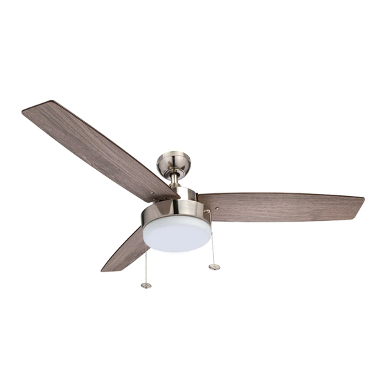
- Page 1 52” STATHAM CEILING FAN Owner’s Manual Models #51019, 51018, 51020 To obtain service, please contact the Service Department: , 9 a.m.- 5 p.m. Central time. 1-877-706-3267 9451 • 061719...
-
Page 2: Package Contents
PACKAGE CONTENTS Unpack your fan and check the contents. You should have the following items: PACKAGE CONTENTS 1. Canopy 12. Motor Screw (x6) 2. Canopy Cover 13. Adapter Plate 3. Mounting Bracket 14. Adapter Plate Screw (x3) 4. Mounting Bracket Screw 15. - Page 3 DIMENSION REFERENCE A. 13.48 in. B. 9.21 in. C. 6.74 in. D. 5.13 in. MOUNTING OPTIONS Dual Mounting Options Angle Ceiling Mount (Up to 16 degrees) Downrod Mount Choose one of the following mounting options: Downrod Mount is best suited for ceilings 8 ft. or higher. For taller ceilings you may want to use a longer downrod (not included).
-
Page 4: Safety Instructions
SAFETY INSTRUCTIONS READ ALL SAFETY INFORMATION AND INSTALLATION INSTRUCTIONS BEFORE YOU BEGIN INSTALLING THE FAN AND SAVE INSTRUCTIONS. CAUTION: All set screws of the fan must be checked and retightened where necessary before installation. To reduce the risk of personal injury, do not bend the blade brackets when installing the brackets, balancing the blades or cleaning fan. - Page 5 ASSEMBLY INSTRUCTIONS 1. Turn OFF the electrical power at the main fuse or circuit breaker. Mounting Mounting 2. Loosen all mounting brackets screws. Remove the Bracket Bracket Screw two mounting bracket screws from the round holes of canopy. Set aside for later use. Detach mounting bracket from canopy.
- Page 6 ASSEMBLY INSTRUCTIONS 5. Remove the downrod clip and downrod pin from the downrod. Then partially loosen the two set screws in the Downrod yoke at the top of the motor. Downrod Clip Downrod Pin Set Screw Yoke Motor 6. Feed the wires coming from the yoke through the yoke cover, canopy, and downrod.
- Page 7 ASSEMBLY INSTRUCTIONS 9. Use wire connectors to connect the fan wires to the Black (hot) power supply wires according to the wiring diagram and the following instructions: White (neutral) • Connect the green wire from the downrod and mounting Bare/Green (ground) bracket to the bare/green (ground) supply wire.
- Page 8 ASSEMBLY INSTRUCTIONS 13. Remove one of the three adapter plate screws from Motor the adapter plate and loosen the other two screws, but do Assembly not remove. Align the keyholes of the light pan with the loosened adapter plate screws, then turn the light pan in a Adapter clockwise direction.
- Page 9 ASSEMBLY INSTRUCTIONS 17. Attach the pull chain extensions to each of the pull chains. Restore the power at the main fuse or circuit breaker. Pull Chain Extension OPERATING INSTRUCTIONS 1. The fan pull chain is located to the right of the reverse switch.
-
Page 10: Troubleshooting
TROUBLESHOOTING If you have difficulty operating your new ceiling fan, it may be the result of incorrect assembly, installation or wiring. In some cases, these installation errors may be mistaken for defects. If you experience any faults, please check the Troubleshooting section below. If a problem cannot be remedied or you are experiencing difficulty in installation, please contact the Service Department: 1-877-706-3267, 9 a.m.- 5 p.m. -
Page 11: Limited Lifetime Warranty
LIMITED LIFETIME WARRANTY To obtain Service, please contact the Service Department: 1-877-706-3267, 9 a.m.- 5 p.m. central time. Model Name: 52” Statham Ceiling Fan Model No: 51019 - Brushed Nickel 51018 - Espresso 51020 - Gun Metal The manufacturer warrants this fan to be free from defects in workmanship and materials present at time of shipment from the factory for a lifetime from the date of purchase by the original purchaser.
Need help?
Do you have a question about the STATHAM and is the answer not in the manual?
Questions and answers