
Subscribe to Our Youtube Channel
Related Manuals for Hoshizaki KM-40C-HC


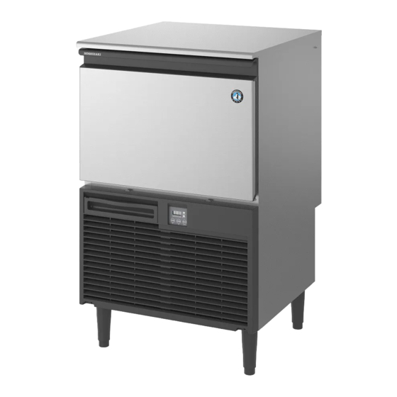
Summary of Contents for Hoshizaki KM-40C-HC
- Page 1 SELF-CONTAINED CRESCENT CUBER KM-40C-HC KM-60C-HC KM-80C-HC SERVICE MANUAL F158-1120 (102921)
-
Page 2: Table Of Contents
1. DIMENSIONS/SPECIFICATIONS --------------------------------------------------------------1 II. GENERAL INFORMATION -------------------------------------------------------------------------2 1. CONSTRUCTION ----------------------------------------------------------------------------------2 [a] KM-40C-HC, KM-60C-HC --------------------------------------------------------------------2 [b] KM-80C-HC --------------------------------------------------------------------------------------3 [c] ICEMAKING COMPARTMENT (KM-40C-HC, KM-60C-HC) ------------------------4 [d] ICEMAKING COMPARTMENT (KM-80C-HC) ------------------------------------------5 2. SEQUENCE OF OPERATION ------------------------------------------------------------------6 [a] BASIC CONTROL -----------------------------------------------------------------------------6 [b] BIN CONTROL ---------------------------------------------------------------------------------8... - Page 3 8. PUMP MOTOR ------------------------------------------------------------------------------------ 64 9. WATER VALVE ------------------------------------------------------------------------------------ 65 10. DRAIN VALVE ------------------------------------------------------------------------------------- 66 11. FLOAT SWITCH ---------------------------------------------------------------------------------- 67 [a] KM-40C-HC, KM-60C-HC ------------------------------------------------------------------ 67 [b] KM-80C-HC ------------------------------------------------------------------------------------ 68 12. BIN CONTROL SWITCH ----------------------------------------------------------------------- 70 13. THERMISTOR ------------------------------------------------------------------------------------ 72 14. CONTROL BOX ---------------------------------------------------------------------------------- 73...
- Page 4 2. MAINTENANCE ---------------------------------------------------------------------------------- 85 [a] MACHINE AND BIN EXTERIOR --------------------------------------------------------- 85 [b] SCOOP AND STORAGE BIN HANDLE CLEANING/SANITISATION (DAILY) ----------------------------------------------------------------------------------------- 85 [c] STORAGE BIN INTERIOR CLEANING/SANITISATION (WEEKLY) ------------ 85 [d] AIR FILTER ------------------------------------------------------------------------------------ 86 [e] CONDENSER --------------------------------------------------------------------------------- 86 3. PREPARING THE ICEMAKER FOR LONG STORAGE -------------------------------- 87...
-
Page 5: Specifications
I. SPECIFICATIONS 1. DIMENSIONS/SPECIFICATIONS Refer to the dimensional drawings available from the “Product Literature Search System”. -
Page 6: General Information
II. GENERAL INFORMATION 1. CONSTRUCTION [a] KM-40C-HC, KM-60C-HC Top Panel Evaporator Separator Door Louver Control Box Operation Switch Fuse Spring Air Filter Fan Motor Condenser Front Frame Drain Valve Thermistor Rear Panel Water Valve Pump Motor Water Inlet Power Supply... -
Page 7: [B] Km-80C
[b] KM-80C-HC Evaporator Top Panel Separator Door Louver Control Box Operation Switch Spring Fuse Air Filter Condenser Fan Motor Front Frame Drain Valve Rear Panel Thermistor Water Valve Pump Motor Float Switch Water Inlet Hose Drain Outlet Hose Power Supply Cord Compressor Drier... -
Page 8: [C] Icemaking Compartment (Km-40C-Hc, Km-60C
[c] ICEMAKING COMPARTMENT (KM-40C-HC, KM-60C-HC) Spray Tube Separator Pump Motor Cube Guide Water Tank Float Switch Water Supply Tube (With Spray Tube Removed) Drain Valve Evaporator Water Valve Bin Control Switch... -
Page 9: [D] Icemaking Compartment (Km-80C
[d] ICEMAKING COMPARTMENT (KM-80C-HC) Spray Tube Separator Cube Guide Water Tank Float Switch Pump Motor Water Supply Tube (With Spray Tube Removed) Drain Valve Water Valve Evaporator Bin Control Switch... -
Page 10: Sequence Of Operation
2. SEQUENCE OF OPERATION [a] BASIC CONTROL... - Page 11 1. Power On When power is supplied, a 5 second delay occurs at startup. Then, the display shows “run”. 2. Fill Cycle WV opens, PM energizes and the fill period begins. Every minute, the board checks for a closed F/S. If F/S is closed, PM de-energizes and the harvest cycle starts. In the sanitation mode (Setting 53), the fill cycle is followed by the “Sanitation Control”.
-
Page 12: [B] Bin Control
[b] BIN CONTROL 1. Drain 2. Standby Fill Cycle Freeze Cycle 20-min Timer 15-min Timer Drain Timer BC open 15 sec BC check BC closed 90 sec or more or more BC Operation PM energized PM de-energized PM energized PM de-energized F/S open DV energized DV de-energized... -
Page 13: [C] Halt Control
[c] HALT CONTROL Harvest 1. Drain 4. Standby 2. Fill 3. Drain Fill Cycle Cycle Drain Timer 2-min Timer Drain Timer 30-sec Timer 20-min Timer 15-min Timer F/S open F/S open PM energized PM de-energized PM energized PM continues PM de-energized PM energized PM de-energized DV energized... -
Page 14: [D] Sanitation Control
[d] SANITATION CONTROL The water circuit is periodically flushed with tap water to keep the circuit clean and sanitary for long hours of inactivity. The sanitation control starts: - in sanitation mode (Setting 53), after the fill cycle or in 4 hours after the beginning of bin control or halt control, or - when the cleaning button is pressed in bin control or halt control. -
Page 15: [E] Water Cleaning Control
[e] WATER CLEANING CONTROL The water circuit is flushed with tap water at the set frequency, while adjusting the PM flow rate, to prevent scaling of the circuit. The water cleaning control starts: - automatically at the set frequency of water cleaning counter (Setting 44), or - when the cleaning button is pressed other than in bin or halt control. -
Page 16: [F] Automated Chemical Cleaning Control
4. Drain Process DV opens in 2 seconds while PM energizes to drain the water tank. If F/S is open (no water in tank), the drain timer starts counting down. When the time is up, DV closes while PM de-energizes. After the end of drain process, the original process is resumed. - Page 17 tank with chemical solution before the time is up. Then, wait until the timer expires or press the cleaning button. 3. Fill Process PM energizes. In 3 seconds: - if F/S is open (no water in tank), it is supposed that chemical solution has not been fed manually.
-
Page 18: [G] Fully Automated Chemical Cleaning Control (Option)
[g] FULLY AUTOMATED CHEMICAL CLEANING CONTROL (OPTION) When the fully automated cleaning kit (option) is installed, the water circuit is cleaned at the set frequency with chemical solution automatically provided to the water tank, while adjusting the PM flow rate, to descale the circuit. The fully automated chemical cleaning control starts at the set frequency of fully automated chemical cleaning (Setting 50): - after the end of harvest cycle for the icemaking operation in 5 hours after the number... - Page 19 6. Chemical Cleaning Process PM energizes to clean the water circuit with chemical solution by adjusting the rotation speed. Then, PM de-energizes. 10 seconds: D (low speed) >> 10 seconds: A (high speed) >> 10 seconds: D (low speed) >> 10 seconds: A (high speed) >> 10 seconds: D (low speed) <Rinse>...
-
Page 21: Control Board
3. CONTROL BOARD [a] INPUT/OUTPUT LAYOUT Program Install Evaporator Thermistor Condenser Thermistor 7-Segment Bin Control Switch LED Thermistor (Option) 3-Digit Display Float Switch Communication 24V DC Input Compressor Relay X3 (Fan Motor) Relay X2 (Water Valve) UV LED (Option) Drain Valve Cleaning System (Option) Relay X1 (Hot Gas Valve) Pump Motor... -
Page 22: [B] Switch Operation
[b] SWITCH OPERATION [1] Display run: Icemaking oFF: Shut down FUL: Bin full cln: Cleaning [2] Dot Off: Normal mode Normal Mode Sanitation Mode On: Sanitation mode (*) * After 4 continued hours of inactivity, the icemaker automatically cleans and refreshes the water circuit to prevent bacterial proliferation, keeping it clean and sanitary for longer periods of time. -
Page 23: [C] Model Code Setting
[5] Reset Button / Enter Button 1) When pressed during the fully automated chemical cleaning, the unit starts the rinse process and finishes the fully automated chemical cleaning. 2) When pressed with an error code in the display, the unit determines whether to reset the error. - Page 24 When chemical doses reach set Number of chemical U.49 number of times, notice code "n93" 15 times 3 times 1 time doses appears to show no chemical is left. Fully automated Start fully automated chemical cleaning 1000 U.50 chemical cleaning at set frequency.
-
Page 25: [E] Service Mode
[e] SERVICE MODE The settings listed below are monitored and adjusted by service personnel. 1) Press and hold the reset button and press the cleaning button three times to enter the service mode. The display shows one of the setting codes. 2) Use the up or down button until the display shows the desired setting code. - Page 26 0: No control 1: If evaporator thermistor reads 5°C or less, pump motor de-energizes for 10 seconds. 2: If evaporator thermistor reads 10°C or less, pump motor repeats de-energizing 12 Slush ice control – for 10 seconds and energizing for 50 seconds.
- Page 27 When "drn" is selected, unit de-energizes every component, drain ("drn"), and shuts 59 Forced drain – – down ("oFF"). If reset button is pressed during drain cycle, unit shuts down. Notice (e.g. Notice code “n99” appears after set period of 6000 0 hrs 100 hrs...
-
Page 28: [F] 7-Segment Display
[f] 7-SEGMENT DISPLAY Normal Mode Sanitation Mode Mode Change Icemaking Bin Full Shut Down Water Cleaning Automated Chemical Chemical Cleaning Cleaning Rinse Drain Fully Automated Chemical Water Cleaning Cleaning Pre-feed Feed & Chemical Cleaning Rinse Flush Drain... -
Page 29: [G] Error Codes
Normal Mode Sanitation Mode [g] ERROR CODES Shut down The display flashes an error code (e.g. “E40” >> blank >> “E40” >> blank >> ...), and the unit shuts down. This will repeat even if the main power supply is turned off and back Press the reset button to restart the unit. - Page 30 Error Codes Code Item Description Operation Reset LED thermistor LED thermistor circuit is open. Shut down Press reset button error Control board memory or setting error Replace control E40 Setting error Shut down is detected. board IC storing model code setting data is Replace control E41 EEPROM error Shut down...
- Page 31 n32 LED error LED temperature fails to rise. Continue Replace LED Fully automated Turn off power Water circuit fails to flush properly. Continue cleaning error supply Float switch fails to close at lower Automatically reset n70 Low water float level four times in a row when Halt in 10 minutes (fill checked every minute in fill cycle.
- Page 32 Hot gas valve Opening failure Replace coil or valve Hot gas valve relay Coil circuit open Replace Water valve Opening failure Clean or replace Water valve relay Coil circuit open Replace Locked Replace Pump motor Low RPM Replace motor or control board Hot gas valve Closing failure Replace...
-
Page 33: Thermistor
Pump motor Locked Replace Pump motor discharge Disconnected Reconnect hose Hot gas valve Closing failure Replace Hot gas valve relay Bad contacts Replace Drain valve Opening failure Replace Locked Replace Pump motor Low RPM Replace motor or control board Float sticking Descale Float switch Bad contacts... -
Page 34: Bin Control
Temperature (°F) Temperature (°C) Resistance (k Ω ) 14.401 10.613 6.000 3.871 2.474 1.633 Check a thermistor for resistance by using the following procedure: 1) Disconnect the connector CN6 on the board. 2) Remove the thermistor. See “V. 13. THERMISTOR”. 3) Immerse the thermistor sensor portion in a glass containing ice and water for 2 or 3 minutes. - Page 35 2) Clear any ice away from the bin control. 3) If the bin control is calling for ice (proximity switch closed) for more than 90 seconds, the display shows “run” and the fill cycle starts. 4) Activate the bin control actuator (press the actuator in) for more than 15 seconds (proximity switch open).
-
Page 36: Technical Information
III. TECHNICAL INFORMATION 1. WATER CIRCUIT AND REFRIGERANT CIRCUIT [a] KM-40C-HC, KM-60C-HC Water Inlet Capillary Tube Accumulator Water Spray Tube Valve Drain Thermistor Valve Pump Motor Evaporator Water Tank Float Switch Drain Outlet Hot Gas Condenser Drier Valve Compressor Water Circuit... -
Page 37: [B] Km-80C-Hc
[b] KM-80C-HC Water Inlet Water Valve Expansion Valve Spray Tube Drain Valve Thermistor Evaporator Water Tank Pump Motor Float Switch Drain Outlet Hot Gas Valve Compressor Thermistor Drier Condenser Water Circuit Refrigeration Circuit... -
Page 38: Wiring Diagram
2. WIRING DIAGRAM [a] KM-40C-HC, KM-60C-HC... -
Page 39: [B] Km-80C-Hc
[b] KM-80C-HC... -
Page 40: Timing Chart
3. TIMING CHART [a] BASIC AND BIN CONTROLS... -
Page 42: [B] Sanitation (Sanitation Mode)
[b] SANITATION (SANITATION MODE) -
Page 43: [C] Halt
[c] HALT... -
Page 44: [D] Sanitation (Cleaning Button)
[d] SANITATION (CLEANING BUTTON) -
Page 45: [E] Water Cleaning
[e] WATER CLEANING... -
Page 50: Service Diagnosis
(9) In 5 seconds, the drain valve closes and the cleaning valve (*) opens. (10) In 5 seconds, the cleaning valve closes and every load de-energizes to go back to step (1) above. * The water valve 2 and cleaning valve are not provided for KM-40C-HC, KM-60C- HC and KM-80C-HC. -
Page 51: Ice Production
2. NO ICE PRODUCTION PROBLEM POSSIBLE CAUSE REMEDY [1] The icemaker will a) Power Supply 1. Unplugged. 1. Plug in. not start. 2. Loose connections. 2. Tighten. 3. Bad contacts. 3. Check for continuity and replace. 4. Voltage too high. 4. - Page 52 PROBLEM POSSIBLE CAUSE REMEDY [3] Compressor a) Overload Protector 1. Bad contacts. 1. Check for continuity and will not start replace. or operates 2. Voltage too low. 2. Increase voltage. intermittently. 3. Refrigerant 3. Recharge. overcharged or undercharged. b) Starter 1.
- Page 53 PROBLEM POSSIBLE CAUSE REMEDY [5] No water comes a) Water Supply Line 1. Water pressure too low 1. Check and get from spray tubes. and water level in water recommended pressure. Water pump tank too low. will not start, or b) Inlet Water Valve 1.
-
Page 54: Evaporator Is Frozen Up
3. EVAPORATOR IS FROZEN UP PROBLEM POSSIBLE CAUSE REMEDY [1] Freeze cycle a) Float Switch 1. Leads shorted or 1. Check and replace. time is too long. defective switch. 2. Float does not move 2. Clean or replace. freely. b) Inlet Water Valve 1. -
Page 55: Low Ice Production
4. LOW ICE PRODUCTION PROBLEM POSSIBLE CAUSE REMEDY [1] Freeze cycle a) See chart 2 - [3] and check dirty air filter or condenser, ambient or water time is long. temperature, water pressure, and refrigerant charge. b) See chart 2 - [7] and check refrigerant, compressor, and hot gas solenoid valve. -
Page 56: Other
6. OTHER PROBLEM POSSIBLE CAUSE REMEDY [1] Icemaker will not a) Bin Control Switch 1. Completely 1. Place in position. stop when bin is disconnected and filled with ice. dropped inside bin. 2. Detector broken. 2. Replace. 3. Detector out of 3. -
Page 57: Removal And Replacement
V. REMOVAL AND REPLACEMENT WARNING Only trained service engineer can service the R290 refrigeration unit. 1. SERVICE FOR REFRIGERANT LINES [a] SERVICE INFORMATION 1) Allowable Compressor Opening Time and Prevention of Lubricant Mixture [R290] The compressor must not be opened more than 30 minutes in replacement or service. Do not mix lubricants of different compressors even if both are charged with the same refrigerant, except when they use the same lubricant. -
Page 58: [B] Refrigerant Recovery
6) Replacement Copper Tubing [R290] The copper tubes currently in use are suitable for R290. But do not use them if oily inside. The residual oil in copper tubes should be as little as possible. (Low residual oil type copper tubes are used in the shipped units.) 7) Evacuation, Vacuum Pump and Refrigerant Charge [R290] Never allow the oil in the vacuum pump to flow backward. -
Page 59: [D] Evacuation And Recharge
When removing the refrigerant from the unit, be sure the surrounding area is well- ventilated and free from open flames. Discharge refrigerant in small amounts into the atmosphere. If the surrounding area is not well-ventilated and exposed to open flames, recover the refrigerant in a refrigerant recovery cylinder and discharge it in small amounts into the atmosphere outdoors. -
Page 60: Welding Repair For R290 Refrigeration Circuit
2. WELDING REPAIR FOR R290 REFRIGERATION CIRCUIT 1) Make sure the surrounding area of the unit to be repaired is free from ignition sources. 2) Open the window or operate the ventilator to make the surrounding area well- ventilated. 3) Connect the piercing valve. Recover the refrigerant in the specified manner or discharge it into the atmosphere. -
Page 61: Compressor
3. COMPRESSOR WARNING The compressor terminal cover must be refitted in its correct position. Otherwise, operation under high temperature and high humidity conditions may cause electric shock, fire, or corrosion to shorten the service life. IMPORTANT Always install a new drier every time the sealed refrigeration system is opened. -
Page 62: Drier
16) Connect the solderless terminals, and replace the terminal cover in its correct position. 17) Refit the louver and rear cover in their correct positions. 18) Plug in the icemaker. Note: Hoshizaki recommends that compressor starting electrics are always replaced at the same time as the compressor. 4. DRIER IMPORTANT Always install a new drier every time the sealed refrigeration system is opened. -
Page 63: Hot Gas Valve
5. HOT GAS VALVE CAUTION To ensure optimum performance, use a copper tube of the same diameter and length for replacement of the hot gas circuit. IMPORTANT Always install a new drier every time the sealed refrigeration system is opened. Do not replace the drier until after all other repair or replacement has been made. - Page 64 7) Braze the new hot gas valve with nitrogen gas flowing at a pressure of 0.2 - 0.3 bar. WARNING Always protect the valve body by using a damp cloth to prevent the valve from overheating. Do not braze with the valve body exceeding 135°C. 8) Install the new drier (see “V.
-
Page 65: Expansion Valve - Km-80C-Hc Only
6. EXPANSION VALVE - KM-80C-HC ONLY IMPORTANT The water in the refrigeration circuit may exceed the capacity of the Drier and freeze in the Expansion Valve. Always install a new Drier every time the sealed refrigeration system is opened. Do not replace the Drier until after all other repair or replacement has been made. - Page 66 Top Rear View with Top and Rear Panels Removed Remove expansion valve cover first Cut ties to make bulb removable Bulb Insulation Hose Wrap this part with a damp cloth to prevent overheating Expansion Valve Expansion valve is brazed at these two points.
-
Page 67: Fan Motor
7. FAN MOTOR 1) Unplug the icemaker. 2) Remove the louver. 3) Disconnect the connector of the fan motor lead. 4) Remove the two screws securing the fan motor bracket, and pull out the fan motor in the arrow direction. To prevent deformation, do not hit the fan on the condenser or other parts. -
Page 68: Pump Motor
8. PUMP MOTOR 1) Unplug the icemaker. 2) Remove the top panel, and unscrew the rear panel. 3) Disconnect the connector of the pump motor lead. 4) Remove the water tank (see “V. 15. WATER TANK”). 5) Remove the ties connecting the pump motor discharge outlet, and pull off the silicone hose. -
Page 69: Water Valve
9. WATER VALVE 1) Unplug the icemaker. 2) Close the water supply tap. 3) Remove the top panel, and unscrew the rear panel. 4) Disconnect the tab terminals. 5) Pinch and lower the hose clamp. 6) Disconnect the rubber hose from the water valve. Put a towel under the water valve to receive water coming out. -
Page 70: Drain Valve
10. DRAIN VALVE 1) Unplug the icemaker. 2) Close the water supply tap. 3) Remove the top panel, and unscrew the rear panel. 4) Remove the water valve (see “V. 9. WATER VALVE”). 5) Disconnect the connectors (or tab terminals) of the drain valve lead. 6) Pinch and shift the two hose clamps. -
Page 71: Float Switch
11. FLOAT SWITCH [a] KM-40C-HC, KM-60C-HC 1) Unplug the icemaker. 2) Remove the top panel, and unscrew the rear panel. 3) Disconnect the connector of the float switch lead and remove the lead wire from the grommet through the slit. -
Page 72: [B] Km-80C-Hc
[b] KM-80C-HC 1) Unplug the icemaker. 2) Remove the top panel, and unscrew the rear panel. 3) Disconnect the connector of the float switch lead (gray). 4) The float switch is located behind the pump motor. Pinch the arrowed part (1) and pull it diagonally forward (2) to unhook the float switch. - Page 73 7) Put the float switch down into the mounting hole and hook it in position as shown. To ensure proper operation, be sure to fit the hook (A) under the mounting hole. 8) Refit the removed parts in the reverse order of the removal procedure. 9) Plug in the icemaker.
-
Page 74: Bin Control Switch
6) Hold both sides of the bin control switch and pull it toward you. Pull Retainer Stopper (A) [both sides] Bin Control Switch Hold here and pull toward you Slide Rail [both sides] 7) The bin control switch (KM-40C-HC) pulled out of the storage bin has the internal structure as shown below. - Page 75 Reed Switch Lead Hook Stopper (B) [both sides] * Fit in stopper (A) Bin Switch Case Bin Switch Plate Reed Switch Cover 8) To remove the bin switch plate, slightly warp both sides and pull the shaft toward you. Slightly warp Top View Pull toward you 9) Refit the removed parts in the reverse order of the removal procedure.
-
Page 76: Thermistor
13. THERMISTOR 1) Unplug the icemaker. 2) Remove the top panel, and unscrew the rear panel. 3) Disconnect the connector of the thermistor lead (orange). 4) Remove the ties, insulation, thermistor holder, and thermistor in this order. 5) Remove the old sealant from the thermistor holder and suction pipe. 6) Wipe off any moisture or condensation from the suction pipe surfaces. -
Page 77: Control Box
14. CONTROL BOX 1) Unplug the icemaker. 2) Remove the louver. 3) Remove the two mounting screws, and pull the control box toward you. 4) To refit the control box, push it in horizontally. Operation Board Fuse Fuse Holder Control Box Relay Board Support Screw... -
Page 78: [C] Control Board
[c] CONTROL BOARD 1) Disconnect all the connectors. 2) Release the control board from the board support. 3) Install the new control board in the reverse order of the removal procedure. 4) When reconnecting the connectors, do not push them too hard. The control board may be damaged. -
Page 79: [F] Relay
[f] RELAY 1) Disconnect the tab terminals. 2) Remove the mounting screw. 3) Install the new relay in the reverse order of the removal procedure. 4) To prevent miswiring, check the terminal numbers and lead wire colors with the wiring label. 15. - Page 80 3) Pinch and push down the snaps on both sides of the bracket to unhook the water tank from the square holes, and pull it about 1” toward you. Snap Water Tank 4) When the snaps are unhooked from the square holes, the rear part of the water tank (dotted circle below) is also unhooked.
-
Page 81: Cube Guide
6) Slide the left side of the water tank to release it from the bracket rail, lift down the entire water tank, and pull it toward you out of the storage bin. Do not hit the other components. 7) Refit the water tank in the reverse order Bracket Rail of the removal procedure (left, right, top, rear). -
Page 82: Separator
17. SEPARATOR 1) Unplug the icemaker. 2) Remove the screws at the rear, and take off the top panel. 3) Hold both sides of the separator from the top. Bend the front separator into a U-shape and remove it from the shaft of the evaporator bracket. Bend the rear separator into an inverted U-shape and lift it off the shaft of the evaporator bracket. - Page 83 5) The water supply pipe is located right under the spray tube. Remove the water supply pipe from the evaporator, pinch and shift the hose clamp, and disconnect the hose. 6) The spray guide is located under the water supply pipe. Pull off the spray guide from the evaporator plate.
-
Page 84: Door, Door Stopper, Door Spring, Hook, Slope, Louver
19. DOOR, DOOR STOPPER, DOOR SPRING, HOOK, SLOPE, LOUVER 1) Remove the two mounting screws. Hold the bottom of the louver, pull it toward you, and lift it off (1 cm). Door 2) Unhook the door spring. Hook Louver Door Spring 3) Open the door. -
Page 85: Top Panel, Front Frame
20. TOP PANEL, FRONT FRAME 1) Loosen the two screws at the rear of the icemaker, and remove the top panel. 2) Remove the two screws, and take off the front frame. 3) Refit the removed parts in the reverse order of the removal procedure. * Hook the top of the front frame on the top panel. -
Page 86: Cleaning And Maintenance Instructions
1. CLEANING WARNING 1. Hoshizaki recommends cleaning this unit at least once a year. More frequent cleaning, however, may be required in some existing water conditions. 2. To prevent injury to individuals and damage to the icemaker, do not use ammonia type cleaners. -
Page 87: [B] Parts
Water Tank “run” during the icemaking operation starts to flash “run”. 4) When the display changes to “cln”, pour the following amount of solution into the water tank carefully not to overflow it. KM-40C-HC: 2.0 litres KM-60C-HC: 2.5 litres KM-80C-HC: 3.0 litres... - Page 88 40C/60C-HC. The float switch location is different for KM- 80C-HC (behind the pump motor). Cube Guide Water Tank Cube Guide Water Tank * This illustration shows KM-40C-HC. Snap The following number of cube guides are provided: KM-40C-HC 2 pcs KM-60C-HC 3 pcs...
-
Page 89: Maintenance
1) Either mix 3 litres of water with 11 ml of 5.25% sodium hypochlorite solution in a suitable container, or the recommended Hoshizaki sanitiser as directed. 2) Soak the scoop in the solution for more than 3 minutes. Rinse thoroughly, and shake to remove surplus liquid. -
Page 90: [D] Air Filter
6) Soak a clean sponge or cloth with the solution, and wipe the bin liner, bin door, slope and scoop holder. Note: Clean every surface of the door gasket which gets soiled easily. It is readily removable for cleaning. IMPORTANT No magnet at bottom The door gasket is provided with a magnet... -
Page 91: Preparing The Icemaker For Long Storage
3. PREPARING THE ICEMAKER FOR LONG STORAGE IMPORTANT When shutting off the icemaker for an extended time, drain out all water from the water lines and remove the ice from the storage bin. The storage bin should be cleaned and dried. Drain the water supply lines to prevent their damage at sub-freezing temperatures.
Need help?
Do you have a question about the KM-40C-HC and is the answer not in the manual?
Questions and answers