
Related Manuals for Singer One Plus


Summary of Contents for Singer One Plus
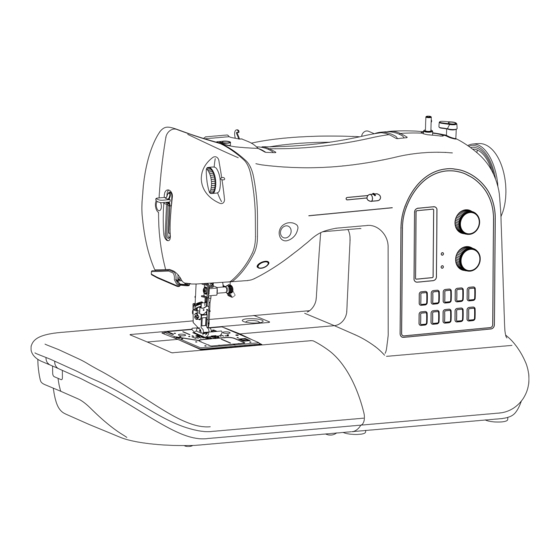
- Page 1 Original issue Service Manual Oct.2012 Page 1/41 Model One Plus MODEL One Plus Original issue: Oct.2012...
- Page 2 Original issue Service Manual Oct.2012 Page 2/41 Model INDEX One Plus 1. Disassembling of covers 2. Test mode 3. Adjustment of feed dog height 4. Needle bar height 5. Needle threader height 6. Presser foot height and direction 7. Needle position at zigzag stitching 8.
- Page 3 Original issue Service Manual Oct.2012 Page 3/41 Model 1. Disassembling of covers One Plus (1) Face cover side Remove screw A. Remove screw B.
- Page 4 Original issue Service Manual Oct.2012 Page 4/41 Model 1. Disassembling of covers –continued-- One Plus (2) Bottom side Remove a screw on front cover. Remove a screw inside of access hole of front cover. Don’t remove screws above and below the access hole...
- Page 5 Original issue Service Manual Oct.2012 Page 5/41 Model 1. Disassembling of covers –continued-- One Plus (3) Back cover side Remove two self-tapping screws. Remove two self-tapping screws Remove self-tapping screw.
- Page 6 Original issue Service Manual Oct.2012 Page 6/41 Model 1. Disassembling of covers –continued-- One Plus (4) Front cover side Loosen screw A.
- Page 7 Service Manual Oct.2012 Page 7/41 Model 1. Disassembling of covers –continued-- One Plus Open back and front covers. Push up front cover to open by inserting small screw driver between front and back covers. Open mating portion of front and back covers by pushing back cover with small screw driver.
- Page 8 Page 8/41 Model 2. Test mode with warning function deactivated One Plus This test mode is used to operate machine without threading, while sensors for thread breakage, presser foot lever and bobbin thread are deactivated. 1. While pushing three switch buttons 1, 3 & 5 at control panel at the same time, turn on sewing machine.
- Page 9 Original issue Service Manual Oct.2012 Page 9/41 Model 2. Test mode -- continued -- One Plus 1. Push bobbin winder to the right 2. Push and hold reverse switch in place. 3. Turn on power switch. 4. Release bobbin winder while pushing reverse switch, just after power switch is turned on.
- Page 10 Oct.2012 Page 10/41 Model 2. Test mode -- continued -- One Plus Release bobbin winder by the time when LED is lit at extreme right line. After entering test mode, the machine beeps and LED turns off. Test mode *Test mode 1 (Button ①)
-
Page 11: Adjustment Of Feed Dog Height
Service Manual Oct.2012 Page 11/41 Model Adjustment of feed dog height One Plus Checking: 1. Move feed dog to its highest position by turning hand wheel. Check to see if feed dog height is as illustrated below. 0.9 – 1.1 mm Adjustment: 1. -
Page 12: Needle Bar Height
4. Needle bar height One Plus Note: Make this checking before checking “Needle timing to shuttle” and ”Feed-dog timing (vertical motion)”. Use needle Singer 90/14. Checking: 1. Select straight stitch at center needle position. 2. Remove presser foot and needle plate, and then remove bobbin case. - Page 13 Page 13/41 Model 4. Needle bar height –continued-- One Plus 3. Tighten the screw (A) securely after adjustment. Replace needle gauge with normal needle #90/14. 4. Check to see if needle threader operates correctly and there is not interference in...
-
Page 14: Needle Threader Height
Model 5. Needle threader height One Plus 1. Use needle Singer 90/14. 2. Select straight stitch at center needle position. 3. Raise needle to its highest position by turning hand wheel toward you. 4. Lowering needle threader lever, check and see if hook is inserted into needle hole. - Page 15 Service Manual Oct.2012 Page 15/41 Model 5. Needle threader height --continued-- One Plus 7. If the direction of insert hook is deviated from correct position, adjust the hook position with the small screw driver in the accessory. Hook Needle hole 8.
- Page 16 Oct.2012 Page 16/41 Model 5. Needle threader height --continued-- One Plus Remove screw (K) and outer pipe (J). Pull down the threading lever to its lowest position. Check and see if hook protrudes approx. 1.5mm from needle. approx.1.5mm Loosen nut (F) under threader support shaft and turn hook portion (G) in either way for adjustment.
- Page 17 Page 17/41 Model 5. Needle threader height -- continued -- One Plus 9. If twin thread guide (H) is located much higher or lower than hook portion, needle is not threaded. After checking hook position, adjust position of outer pipe (J) so that there may be a clearance 0.4 to 0.6 mm between screw (K) and bottom of long hole.
- Page 18 Service Manual Oct.2012 Page 18/41 Model 6. Presser foot height and direction One Plus Checking 5.6 mm 1. Lower the feed dog below the needle plate. 2. Raise the presser foot lever. 3. Check and see if clearance between needle plate and presser foot is about 5.6 mm.
- Page 19 Oct.2012 Page 19/41 Model 7. Needle position at zigzag stitching One Plus Checking: 1. Set test mode at 1. 2. Turn hand wheel by hand and see if needle leaves the same clearance at both right and left end of needle plate hole.
-
Page 20: Clearance Between Needle And Shuttle
Oct.2012 Page 20/41 Model 8. Clearance between needle and shuttle One Plus Note: Set machine at test mode and select mode 1 for needle at L/C/R positions. Make this checking before checking “Needle timing to shuttle”. Checking: 1. Remove needle plate, bobbin case and face cover. - Page 21 Page 21/41 Model 8. Clearance between needle and shuttle --continued-- One Plus 2. If needle clearance to shuttle at right and left position is not same, adjust position of fulcrum (B) for needle swing support. Loosen bolt (C) located under bottom of support plate and adjust position of fulcrum.
- Page 22 Page 22/41 Model 9. Needle timing to feed dog One Plus Note: After adjustment, be sure to follow “Needle timing to shuttle”. As horizontal and vertical feed motion is unitized on this model, adjustment of feed timing is as follows: Checking: 1.
- Page 23 Oct.2012 Page 23/41 Model 10. Needle timing to shuttle hook One Plus Check “Feed timing (vertical movement)” and “Needle height” beforehand. Checking 1. Set machine at test mode and select mode 1. 2. Remove needle plate. Check to see if needle is not bent.
- Page 24 Oct.2012 Page 24/41 Model 10. Needle timing to shuttle hook --continued-- One Plus 2.Tighten screws securely after adjustment. Meshing condition of shuttle race gear and lower shaft gear 1. Check meshing condition of gears after adjustment. Check play of the gear at 4 positions –each 90 degree angle of 1 rotation of shuttle race.
- Page 25 Page 25/41 Model 11. Adjustment of timing of take-up lever to needle One Plus Checking 1. Bring needle bar to its lowest position. 2. Check to see if arm of take-up lever (A) is located at position (C) where one of 3...
- Page 26 Page 26/41 12. Adjustment of meshing position of gears for Model take-up lever One Plus Checking 1. If excessive noise is generated from take-up lever, there should be a problem in meshing of take-up operating gear (A) with main shaft gear.
-
Page 27: Adjustment Of Thread Tension
Service Manual Oct.2012 Page 27/41 Model 13. Adjustment of thread tension One Plus Checking: 1. Set thread tension at the center of “AUTO” position. 2. Pull thread between tension discs and check thread tension value with two twisted Polyester #50 thread. -
Page 28: Tension Of Timing Belt
Page 28/41 Model 14. Tension of timing belt One Plus Note: This checking is needed before and after adjusting “Needle timing to shuttle”. 1. Timing belt is engaged with gears on main and lower shafts. Too weak tension may result in slippage between shuttle gear and lower shaft gear due to thread jamming, bunching and fabric snagging. -
Page 29: Motor Belt Tension
Oct.2012 Page 29/41 Model 15. Motor belt tension One Plus Adjustment: 1. Remove the front cover. 2. Loosen two nuts (A) and adjust belt tension so that belt may be bent about 5 mm when it is pushed by pressure of 100g between upper shaft and motor. -
Page 30: Retaining Bracket For Bobbin Case
Page 30/41 Model 16. Retaining bracket for bobbin case One Plus 1. Remove needle plate. 2. Loosen screw (A) and adjust the position of retaining bracket in direction as illustrated by arrow in fig.1 so that the projection of bobbin case may be positioned against the plate spring in fig.2. - Page 31 Service Manual Oct.2012 Page 31/41 Model 17. Origin point positioning of zigzag bight One Plus Checking meshing position of gears This procedure is needed only when disassembling and re-assembling cams. Checking 1. Remove face cover and turn off power switch.
- Page 32 Page 32/41 Model Origin point positioning of zigzag bight --continued-- One Plus 3. Power off and tighten remaining screw by rotating pinion gear (a) anti clockwise moderately. Note: Unlike other models, this one does not have switch for origin point positioning.
-
Page 33: Stitch Length
Page 33/41 Model 18. Stitch length One Plus (A) Checking meshing position of gears This procedure is needed only when disassembling and re-assembling cams. Rotate motor gear clockwise to touch it with stopper pin and mesh these gears so that... - Page 34 Oct.2012 Page 34/41 Model 18. Stitch length --continued-- One Plus In case of large deviation, adjust as follows: Setting 1. Turn off power switch. 2. Loosen two screws on motor gear. The motor gear will become free from motor shaft.
- Page 35 Service Manual Oct.2012 Page 35/41 Model 18. Stitch length --continued-- One Plus This completes point positioning. (C) Stitch balance If forward and reverse pitch is not balanced due to imperfect zero feed adjustment, adjust by changing position of motor. Adjustment 1.
- Page 36 Page 36/41 Model 18. Stitch length (Full-step version) --continued-- One Plus Adjustment without removing front and rear covers 1. Lay machine on its back and remove cap with small screw driver. 2. Loosen screw (A) with L-shaped 5 mm hex driver.
- Page 37 Service Manual Oct.2012 Page 37/41 Model 19. Needle stops at highest position One Plus Needle always stops at high position. This is controlled by sensor cam and sensor located on main shaft. Adjustment: 1. Raise needle to its highest position.
- Page 38 Original issue Service Manual Oct.2012 Page 38/41 Model 20. Electronic component area One Plus AC Power Board 87625 is for 120V spec. and is for 230V spec. 87629 Be sure to check number printed on board. 87625 & 87629 Transformer...
- Page 39 Original issue Service Manual Oct.2012 Page 39/41 Model 20. Electronic component area -- continued -- One Plus CPU Board One Plus 84185...
- Page 40 Original issue Service Manual Oct.2012 Page 40/41 Model 20. Electronic component area -- continued -- One Plus Switch Board One Plus Check number printed on board. 84182...
-
Page 41: Wiring Diagram
Original issue Service Manual Oct.2012 Page 41/41 Model 21. Wiring diagram One Plus Model One Plus...
Need help?
Do you have a question about the One Plus and is the answer not in the manual?
Questions and answers