Table of Contents
Advertisement
Quick Links
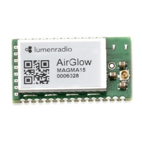
AirGlow radio module integration guide
Product Description
The AirGlow technology combines advanced
wireless outdoor lighting control with unique
scalability and future IoT possibilities. The
AirGlow module comes with the same feature
set as the AirGlow device. It has a built in
advanced wireless lighting control based on
LumenRadio's reliable patented wireless
MiraMesh technology.
MiraMesh is a self-contained self-healing
wireless mesh without the need of a gateway
or other specific hardware.
AirGlow embodies LumenRadio's many years
of experience in wireless lighting control from
high-stakes applications such as Film &
Broadcasting Lighting and Architectural
Lighting.
The AirGlow module is fully compliant with
ETSI EN 300 328 (v2.2.2) is FCC/IC certified
with a modular approval up to 100mW.
Manufacturers can add AirGlow to their
products easily with full OrCAD, Allegro and
DXF symbol libraries available to simply drop
onto existing layouts. AirGlow is fully DALI2
and D4i compliant and only a few extra
external components are required for built in
wireless DALI based light controls.
An AirGlow development kit is available for
purchase and can be used to evaluate
performance and is also good resource when
integrating the module into a product.
LumenRadio AB
Svangatan 2B
SE-416 68 Gothenburg
Sweden
•
Based on LumenRadio's MiraMesh
technology
•
DALI2 and D4i type D compliant
•
Compliant against ETSI EN 300 328
(v2.2.2)
•
Modular approval FCC/IC certified
•
Compact size with few external
components required.
•
Astronomical time triggering of scenes
•
Time triggering of scenes
•
Presence detection scene triggering
through LSI interface and DALI2/D4i
sensors*
•
Smartphone app for commissioning and
for lighting control setup.
•
Up to 6ch DALI DT6: RGBA/W, CW, WW
•
Sub second response time
•
Firmware over the air upgrade through
app.
*Later release
•
Range: up to 1500m free line of sight
between two devices.
•
Output (ERP): Max 20 dBm
•
Sensitivity: -93dBm
•
U.FL/IPEX external antenna connector
•
Frequency band: 2.45 GHz, ISM band
(2402-2480 MHz)
•
Number of units: Up to 200 in one
meshing network.
•
Number of hops: 8 hops in the meshing
network
•
Dimensions: 18.5 mm x 33.5 mm
•
Supply voltage 3.0 - 3.6V
•
Average current consumption 150mA
www.lumenradio.com
sales@lumenradio.com
Version: 2 March 17, 2022
Features
Specifications
Phone: +46 31 301 03 70
Fax: +46 31 301 03 80
VAT reg. no: SE556761749201
Advertisement
Table of Contents

Related Manuals for LumenRadio AirGlow


Summary of Contents for LumenRadio AirGlow
- Page 1 IoT possibilities. The AirGlow module comes with the same feature set as the AirGlow device. It has a built in advanced wireless lighting control based on Features LumenRadio’s reliable patented wireless MiraMesh technology.
-
Page 2: Table Of Contents
Electrical specification ......................4 Mechanical specification ....................... 5 Pin assignments ........................... 6 Functional Description ........................8 Bluetooth connectivity and AirGlow app ................8 Firmware Update Over the Air ....................8 AirGlow Lighting controller ....................8 Block diagram ..........................9 Power supply recommendations ....................9 DALI Interface .......................... - Page 3 AirGlow radio module integration guide Version: 2 March 17, 2022 14.1.1 FCC Information to User ....................22 14.1.2 FCC Guidelines for Human Exposure ................. 22 14.1.3 FCC Declaration of Conformity ..................22 14.1.4 FCC Radio Frequency Interference Warnings & Instructions¶ ........22 14.2 Industry Canada statement ....................
-
Page 4: Specifications
AirGlow radio module integration guide Version: 2 March 17, 2022 1 Specifications • Range: up to 1500m free line of sight between two meshing devices • Bluetooth range: up to 35m free line of sight • Output (ERP): Max 20 dBm •... -
Page 5: Mechanical Specification
AirGlow radio module integration guide Version: 2 March 17, 2022 1.2 Mechanical specification All dimensions in mm Mechanical design files in .stp and .dxf format is available for download at the LumenRadio online support page for the AirGlow module. LumenRadio AB www.lumenradio.com... -
Page 6: Pin Assignments
AirGlow radio module integration guide Version: 2 March 17, 2022 2 Pin assignments Module seen from the top Name Pin type Description Power Ground (0V) MOSI Digital input SPI Master Out, Slave In (future use) N.C. No connection Do not connect N.C. - Page 7 AirGlow radio module integration guide Version: 2 March 17, 2022 N.C. No connection Do not connect N.C. No connection Do not connect Power Ground (0V) Power Ground (0V) Power Ground (0V) Power Ground (0V) Power Ground (0V) Digital output SPI Interrupt signal, active low (future use) N.C.
-
Page 8: Functional Description
RGB (Red, Green Blue), Amber/White (A), Cold White (CW), Warm White (WW) Scenes are setup in the AirGlow app. A Scene can be triggered by either an input signal on the LSI pin of an AirGlow (typically a presence sensor) or it could be triggered by a specific time on a specific day of the week. -
Page 9: Block Diagram
Version: 2 March 17, 2022 4 Block diagram 5 Power supply recommendations The AirGlow module is designed for 3.3V operation. All pins should not have any power applied to them before the +3.3V rail is applied. To ensure reliable operation the supply pin should be decoupled with a 100nF ceramic capacitor located as close to the supply pins as possible. -
Page 10: Dali Data Interface Reference Design
Version: 2 March 17, 2022 6.1 DALI data interface reference design Below is the schematics and BOM of the DALI interface from the AirGlow shield included in the AirGlow development kit. Please note that adjustments of components values might be needed in... -
Page 11: Dali Psu Reference Design
DALI data interface as the current consumption in idle state will be <2mA for the AirGlow interface and <2mA for the LED driver. If higher supply current capabilities are required for power of a sensor from the DALI bus a more advanced DALI PSU design is required. -
Page 12: Rtc Circuit
Loss of power to the RTC circuit will result in loss of absolute time. If absolute time is lost it will automatically be set when the AirGlow app is used to connect to any powered AirGlow in the network. -
Page 13: Battery Backup Considerations
Time to discharge days If the battery is discharged absolute time will be lost but absolute time will be set once the AirGlow app is connected to any powered AirGlow module in the network. 8 Layout considerations Electrical and mechanical design files are available for download at the LumenRadio online support page for the AirGlow module. -
Page 14: Layout Considerations For The Main Board
Guidelines for optimal performance for future optional internal antenna. The AirGlow module has an external antenna connector option of U.FL. type and will have a future option for an internal antenna. If the internal antenna is planned to be used the following guidelines must be followed. - Page 15 PCB material. Min 5mm to solid objects under and above the AirGlow module antenna area. Note that carrier board thickness can be included in the total distance to solid objects under the antenna. I.e. for a 1.6mm carrier board standoffs needs to be min 3.4mm...
-
Page 16: Recommended Antennas
Min 5mm needs to be min 3.4mm 9 Recommended antennas AirGlow has been tested with the following antennas with good results: PANEL MOUNT DOME ANTENNA FOR OUTDOOR USE A good performing antenna for use where the AirGlow module is embedded into a luminaire. The antenna is mounted through a punch out hole and is weatherproofed with the supplied gasket. - Page 17 MINIATURE INDOOR PUCK ANTENNA This antenna has good performance and a small size. It is used by LumenRadio for AirGlow and is weather protected by the Zhaga enclosure. Full range performance of up to 1500m line of sight can be expected using this antenna together with the AirGlow module.
-
Page 18: Airglow Module Development Kit
Arduino compatible shield is available for download on the AirGlow module support page. 10.1 Zhaga book 18 connector wiring diagram In the development kit two Zhaga book 18 connectors and two AirGlow devices are included. These connectors can be used together with the AirGlow devices and below are two wiring diagrams for a D4i certified and a non D4i certified driver. -
Page 19: Product Verification And Testing
All AirGlow modules are factory tested before being shipped. However, it is advised to perform some level of testing as part of your products overall test process. LumenRadio would be happy to advise on production testing – please contact LumenRadio for advice (for contact information see section 16 “Contact and Ordering information”). -
Page 20: Reel Marking
AirGlow radio module integration guide Version: 2 March 17, 2022 12.2 Reel marking Every reel has an identifier sticker booth on the reel and the reel package. The identifier sticker contains the following information: LumenRadio AB www.lumenradio.com Phone: +46 31 301 03 70 Svangatan 2B sales@lumenradio.com... -
Page 21: Airglow Reflow Soldering Specification
Version: 2 March 17, 2022 13 AirGlow reflow soldering specification AirGlow is a surface mounted device (SMD) designed to be easily integrated into high-volume production lines including reflow soldering to a PCB. It is ultimately the responsibility of the customer to choose the appropriate solder paste and to ensure oven temperatures during reflow meet the requirements of the solder paste. -
Page 22: Compliance Information
14.1.3 FCC Declaration of Conformity We LumenRadio AB Svangatan 2B, 41668 Gothenburg, Sweden, declare under our sole responsibility that 840-2111 AirGlow complies with Part 15 of FCC Rules. Operation is subject to the following two conditions: This device may not cause harmful interference, and this device must accept any interference received, including interference that may cause undesired operation. - Page 23 FCC ID of the certified module as the FCC ID of the host end product. A label displaying the AirGlow module’s FCC ID must be affixed and visible on the host end product for approval FCC IDs are required for host end products with radio transmitters.
- Page 24 LumenRadio AB Svangatan 2B SE-416 68 Gothenburg Sweden Phone: +46 31 301 03 70 www.lumenradio.com sales@lumenradio.com The LumenRadio support team can be reached through our support portal. Product Order Code AirGlow module 400pc reel 820-8301 AirGlow module development kit 820-5001 LumenRadio AB www.lumenradio.com...
Need help?
Do you have a question about the AirGlow and is the answer not in the manual?
Questions and answers