Table of Contents
Advertisement
Quick Links
Pure Line
Water Purifier
Model WE200
Instruction Manual
●
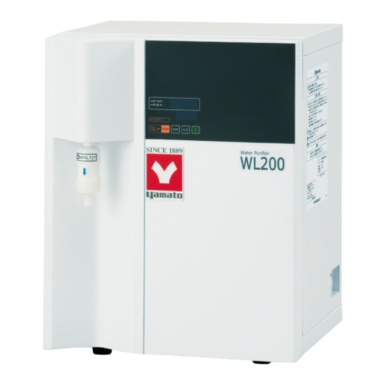
Thank you for choosing the WE200 Pure Line
water purifier by Yamato Scientific Co., Ltd.
●
For proper equipment operation, please read this
instruction manual thoroughly before use. Always
keep equipment documentation safe and close at
hand for convenient future reference.
Warning
: Read instruction manual warnings
Yamato Scientific Co., Ltd.
First Edition
and cautions carefully and
completely before proceeding.
®
Printed on recycled paper
Advertisement
Table of Contents

Subscribe to Our Youtube Channel
Related Manuals for Yamato Pure Line WE200

Summary of Contents for Yamato Pure Line WE200
- Page 1 Instruction Manual First Edition ● Thank you for choosing the WE200 Pure Line water purifier by Yamato Scientific Co., Ltd. ● For proper equipment operation, please read this instruction manual thoroughly before use. Always keep equipment documentation safe and close at hand for convenient future reference.
-
Page 2: Table Of Contents
Table of Contents 1. SAFETY PRECAUTIONS ............. 1 Explanation of Symbols ............... 1 Symbol Glossary ..............2 Warning and Cautions ..............3 2. PRE-OPERATION PROCEDURES ............. 5 Installation ................9 3. COMPONENT NAMES AND FUNCTIONS ..........18 Main Unit ................18 Internal Plumbing System ............ -
Page 3: Safety Precautions
1. SAFETY PRECAUTIONS Explanation of Symbols A Word Regarding Symbols Various symbols are provided throughout this text and on equipment to ensure safe operation. Failure to comprehend the operational hazards and risks associated with these symbols may lead to adverse results as explained below. -
Page 4: Symbol Glossary
1. SAFETY PRECAUTIONS Symbol Glossary WARNING Danger!: High Danger!: Danger!: Moving Danger!: Blast General Warning Voltage Extremely Hot Parts Hazard CAUTION Caution: Do Not Caution: Caution: Caution: May General Caution Heat Without Shock Hazard! Burn Hazard! Leak Water! Water! Caution: Caution: Toxic Water Only Chemicals... -
Page 5: Warning And Cautions
1. SAFETY PRECAUTIONS Warning and Cautions Warning NEVER operate equipment near combustible gases/fumes. Do not install or operate WE200 unit near flammable or explosive gases/fumes. Unit is NOT fire or blast resistant. Negligent use could cause a fire/explosion. See “List of Hazardous Substances” (P.50). ALWAYS ground equipment. - Page 6 1. SAFETY PRECAUTIONS Warning and Cautions Warning DO NOT adjust pressure reduction valve. The pressure reduction valve has a default water sampling rate of approximately 0.8L/min (base water pressure: 0.30MPa, pressure reduction valve: 0.20MPa, throttle valve: 0.60MPa, water temperature: 20°C without membrane filter), as set at factory before shipping.
-
Page 7: Pre-Operation Procedures
Connect grounding wire (green) from (Grounding Resistance Max. 100Ω) is ground adapter to a ground terminal. required in Japan. Contact a local dealer, electrician, or Yamato Sales office for location-specific electrical requirements. 2. Choose an appropriate installation site. DO NOT install unit: ・on uneven or unstable surfaces... - Page 8 2. PRE-OPERATION PROCEDURES Installation Precautions 3. Install in a location free of flammables and explosives. ● Never install near flammables or explosives. This unit is NOT fire or blast resistant. Simply switching the main power switch (ELB) “ON” or “OFF” can produce a spark, which can then be relayed during operation, causing a fire or explosion when near flammable or explosive fluids, chemicals or gases/fumes.
- Page 9 Failure to do so may result in fire or electric shock. Contact a local dealer or Yamato sales office for information about replacing power cable if it becomes damaged.
- Page 10 2. PRE-OPERATION PROCEDURES Installation Precautions 8. Base water. ● Use tap water as base. ● Never use chemicals or lubricants. Malfunction may result and water quality will be compromised. ● Verify that base water does not contain rust or other contaminants. Contaminated base water not only prevents specification-quality water but may also cause malfunction.
-
Page 11: Installation
2. PRE-OPERATION PROCEDURES Installation 1. Connect water supply hose securely. ● Use the included water supply hose kit (connector, water supply hose). Place main unit on a level and stable surface, near a water tap and sink. ● If hose is not connected securely, water supply hose or connector may slip off and cause water to spray or otherwise leak. - Page 12 2. PRE-OPERATION PROCEDURES Installation 3. Make water supply connection. (1) Remove rubber cap from connector plug ⑧. (2) Insert connector plug ⑧ securely into connector socket ⑨ with the sleeve held down in direction of arrow. Sleeve returns to the original position when released, If Valve connection is secure.
- Page 13 2. PRE-OPERATION PROCEDURES Installation 7. Install the ion exchange resin cartridge. ● Turn power off and close water tap before installing or replacing the ion exchange resin cartridge. ●Install procedure: (1) Remove rubber from exchange resin cartridge. (2) Install ion exchange resin cartridge securely into resin...
- Page 14 2. PRE-OPERATION PROCEDURES Installation 8. Install the pre-process cartridge. ●Turn power off and close water tap before installing or replacing the pre-process cartridge. ●Install procedure: Pre-process cartridge (1) Remove rubber cap from the process bracket cartridge. (2) Place pre-process cartridge into designated bracket,...
- Page 15 2. PRE-OPERATION PROCEDURES Installation 9. Install the membrane filter. Install the membrane filter as follows: Unless watertight connection is made, threaded portion may leak fluid which could mix with and contaminate pure water samples. Always ensure a secure, watertight connection.
- Page 16 2. PRE-OPERATION PROCEDURES Installation 10. Connect drain hose. ● Follow the procedures below to connect drain hose. ● Be sure to connect the drain hose securely, or water may leak from connection joint. (1) While holding the quick coupler by hand, push the drain hose completely and evenly into the drain port on the rear of unit.
- Page 17 2. PRE-OPERATION PROCEDURES Installation 13. Install the reverse osmosis (RO) membrane. ● Turn power off and close water tap before installing or replacing the reverse osmosis (RO) membrane. ● WE200 unit is shipped with an RO membrane installed. Review the following when replacing.
- Page 18 2. PRE-OPERATION PROCEDURES Installation 14. Run initial wash for reverse osmosis membrane (after unit delivery and after each time membrane is replaced) Initial wash selector switch ① Remove the four retaining screws from the right cover of main unit and remove cover.
- Page 19 2.PRE-OPERATION PROCEDURES Installation 15. Calibrate pressure for reverse osmosis membrane. ● Calibrate pressure for the RO membrane ONLY while taking a water sample. ● This process must be conducted when WE200 is first installed and each time RO membrane is replaced. ●Pressure calibration procedure: (1) Remove the right cover of main unit and Cover...
-
Page 20: Component Names And Functions
COMPONENT NAMES AND FUNCTIONS Main Unit Pressure Pre-process cartridge calibration Product code:253099 valve Initial wash selector switch Pressure gauge Ion exchange resin reverse osmosis (RO) membrane:RO-1S cartridge:CPC-T Product code:253257 Product code:253256 Leak sensor Optional terminal block location Membrane filter Power cable Water socket supply port... -
Page 21: Internal Plumbing System
3. COMPONENT NAMES AND FUNCTIONS Internal Plumbing System ⑪ ⑧ ⑦ ⑨ ⑫ ⑤ ⑬ ⑩ ⑯ ③ ② ⑭ ④ ① ⑥ ⑮ 1. Pressure reduction valve 9. reverse osmosis (RO) membrane 2. Pressure switch 10. Ion exchange resin cartridge CPC-T 3. - Page 22 3. COMPONENT NAMES AND FUNCTIONS Ion Exchange Water Sampling Process ⑪ ⑧ ⑦ ⑨ ⑤ ⑫ ⑩ ⑬ ⑯ ③ ② ⑭ ④ ⑥ ① ⑮ ● Ion exchange water sampling process route is as follows: ①pressure reduction valve, ③water supply solenoid valve, ④pre-process cartridge, ⑤flow sensor, ⑥pressurizing pump,⑨reverse osmosis (RO) membrane, ⑩ion exchange resin cartridge, ⑪water quality sensor,⑫water sampling solenoid valve, ⑬membrane filter (water sample outlet).
- Page 23 3. COMPONENT NAMES AND FUNCTIONS Initial Wash for RO Membrane ⑪ ⑧ ⑦ ⑨ ⑫ ⑤ ⑬ ⑩ ⑯ ③ ⑭ ② ④ ⑥ ① ⑮ ● Initial wash is necessary for stable quality in the pure water sampling process, by removing filler from new RO membrane cartridges.
- Page 24 3. COMPONENT NAMES AND FUNCTIONS System Flush Function ⑧ ⑪ ⑦ ⑫ ⑨ ⑤ ⑬ ⑩ ③ ⑯ ② ⑭ ④ ① ⑥ ⑮ ● The flush function protects the RO membrane and prevents contamination of water remaining in the pipes by removing foreign matter in the reverse osmosis (RO) membrane. This function is automatic.
-
Page 25: Control Panel
3. COMPONENT NAMES AND FUNCTIONS Control Panel ② ⑦ ③ ⑧ ① ④ ⑤ ⑥ Name Function ① Power key power ON/OFF ② Water quality display Displays quality of ion exchange water Displays errors, wear item replacement alerts and operation ③... -
Page 26: Operation Procedure
4. OPERATION PROCEDURE Prior Confirmation Confirm the following before operating WE200. (1)Inspect water supply and drainage ・Confirm that water supply hose is securely connected. ・Confirm that drain hose runs to sink unobstructed and has no bends or kinks. ・Open water tap. ・Confirm that there are no leaks at connection joint in water supply hose. -
Page 27: Operation Procedure
4. OPERATION PROCEDURE Ion Exchange Water Sampling Procedure Sampling ion exchange water ① Press POWER. ● Water quality appears in the water quality display ② Ion exchange water may be sampled by pressing PUSH. Sample will not stop dispensing after releasing key. ●... -
Page 28: Water Quality Index
4. OPERATION PROCEDURE Water Quality Index Changing water quality index The water quality index may be changed by pressing UNIT . ● Conductivity reading ● Resistivity reading ※Index conversion formula is shown below: Conductivity = Resistivity (Ω・m) = (S/m) Resistivity (Ω・m) Conductivity (S/m) See “How conductivity/resistivity relates to water purity”... -
Page 29: Water Purity Assessment Process
4. OPERATION PROCEDURE Water Purity Assessment Process Electronic conductivity measurement and display The water conductivity meter on the control panel displays the conductivity at the outlets of the ion-exchange resin cartridge and at the distilled water condenser. The value displayed can be used as an indicator for replacing the ion-exchange resin cartridge. -
Page 30: Water Quality Characteristics Data (Reference)
4. OPERATION PROCEDURE Water Quality Characteristics Data (reference) Useful lifespan of ion exchange resin cartridge (reference) Resistivity TOC value 1200 1600 2000 2400 2800 3200 Cumulative water volume (ℓ) Ω・m ※Tap water in Kanagawa・・・Resistivity R: Approx. 0.007×10 TOC (total organic carbon): Approx.800ppb ※Water temp.・・・20°C setting Initial water quality characteristics following ion exchange resin cartridge replacement (reference) -
Page 31: Water Sample Size Data Based On Water Temperature (Reference)
4. OPERATION PROCEDURE Water Sample Size Data Based On Water Temperature (reference) Water temperature in samples range from 10 to 30°C. Samples dispense slower at colder temperatures due to reduced RO membrane transmission pressure at 10°C compared to 30°C. Actual water sample volume may deviate slightly from graph below, depending on unit calibration and RO membrane cartridge used. -
Page 32: Optional Items & Modifications
5. OPTIONAL ITEMS & MODIFICATIONS Optional Components Item name Product Specification Description code Stand (included in connection kit) allows samples Water sampling stand 253266 to be taken from a location apart from main unit. (supplied in connection Membrane filter is installed on stand and a 3m kit) tube is run from membrane filter port on main (OWL40) -
Page 33: Optional Power Cable Accessories
5. OPTIONAL ITEMS & MODIFICATIONS Optional Power Cable Accessories Item name Product Other information code Power cable 255410 Optional power cable with plug meeting Electrical PSE/UL standard Appliances and Material Safety Act, UL standard and CSA. :KP300C TYPE A Plug type (ORE12) :Common for VCTF/SJT3/14AWG Cable type... - Page 34 5. OPTIONAL ITEMS & MODIFICATIONS Optional Water Tap Supplies Table of connection combinations for water supply Cap for standard water supply Water supply port coupler joint A (OWG34)・・・・water pipe hose (with stopper) connection using G1/2 threaded male coupler Connection for chemical tap (hose connection tap) G1/2 G1/2...
-
Page 35: Optional Remote Sampling Terminal
5. OPTIONAL ITEMS & MODIFICATIONS Optional Remote Sampling Terminal The remote sampling terminal allows sampling with an input device from a remote location. Connect a switch or other input device to the Connection terminals remote sampling input terminals, located on right (Terminal block screw size:M4) panel of main unit. -
Page 36: Maintenance Procedures
6. MAINTENANCE PROCEDURES Maintenance Guide Maintenance schedule (conduct daily general inspection for optimal performance) Maintenance/inspection items Interval Additional information Continue drawing samples until Ion exchange resin cartridge When appears in water quality improves and CPC replacement *1 notification clears. (automatic information display (See P.11) recovery) - Page 37 *2 Unit automatically displays replacement notification for this wear item based on sample draw time, beginning when CLR was last pressed to reset notification.
-
Page 38: Ion Exchange Resin Cartridge Replacement
Discretion is therefore advised in preparing spare cartridges. Cartridge shelf life is approximately 4 months. ・ Spent cartridges should be discarded as non-combustible material or returned to Yamato (applicable in Japan only). Use the mailing label supplied with cartridge for returns. Yamato Scientific promotes collection and recycling for preservation of the environment. -
Page 39: Wear Item Replacement Alert Reset
6. MAINTENANCE PROCEDURES Wear Item Replacement Alert Reset The useful life of each replaceable cartridge is determined by cumulative water volume it can reliably filter within a predicted timeframe.*1 The WE200 unit counts the cumulative water volume filter time (in hours) for each cartridge and generates notifications to the user when replacement is needed (See display descriptions on P.41). - Page 40 6. MAINTENANCE PROCEDURES Accumulated Volume Hour Reset Replacing items and resetting volume hours before notification is generated Turn the ELB “ON(|)”. ① ② Press POWER. ③ Pressing holding brings in water quality display and unit enters wear item reset mode. ②...
-
Page 41: Water Supply Hose Filter Maintenance
6. MAINTENANCE PROCEDURES Water Supply Hose Filter Maintenance 1. Turn ELB off (O). Turn water supply tap ④ off. Slide the sleeve in direction of arrow, ① and remove water supply hose from the connection port. ⑤ ② 2. Remove plug ② from ring ①... -
Page 42: Extended Storage & Disposal
7. EXTENDED STORAGE & DISPOSAL Warning 1. Equipment disposal ● Discard as bulky waste. ● Do not leave unit unattended, or in a location where children may have access. 2. Maintaining water quality and RO membrane stability ● As a rule, see that the following elements are maintained to keep automatic flush function enabled. -
Page 43: Disposal Considerations
Dispose of or recycle this unit in a responsible and environmentally friendly manner. Yamato Scientific Co., Ltd. strongly recommends disassembling unit, as far as is possible, in order to separate parts and recycle them in contribution to preserving the global environment. -
Page 44: Troubleshooting
8. TROUBLESHOOTING Error Codes Error Code Troubleshooting When an error appears in information display, record details of error, turn ELB “OFF (o)” immediately and shut off water supply tap. If an abnormality occurs, component replacement or unit inspection may be necessary. Contact a local dealer or sales office for assistance. Be prepared to give unit serial number, specific error details and background when making service calls. - Page 45 8. TROUBLESHOOTING Error Codes Other indications Error code Possible causes Solution Measurable upper limit of water Press PUSH to begin drawing sample. If quality range been numeric values fail to exceeded appear during or after ・Conductivity <0.05x10 taking sample, call for service.
-
Page 46: Malfunctions
8. TROUBLESHOOTING Malfunctions More on leak detection error ●Confirmation 1. Confirm that the water supply connection coupler and quick couplers on ion exchange resin cartridge, pre-process cartridge and the Reverse Osmosis (RO) membrane are securely connected. * If leaks are discovered coming from unit plumbing system, turn ELB off immediately, shut off main water supply tap and contact local dealer or sales office for assistance. - Page 47 8. TROUBLESHOOTING Malfunctions Countermeasures Symptom Possibility of a malfunction Reinsert the power cable ● Power cable not connected securely Confirm connection No power ● Facility power supply is defective or Confirm facility power supply is does not properly meet unit rating single phase AC100V~240V ●...
-
Page 48: Service & Repair
When a problem occurs, terminate operation immediately, turn off main power switch (ELB) and disconnect power cable. Contact a local dealer or Yamato sales office for assistance. The following information is required for all repairs. Refer to serial no. and rating ●... -
Page 49: Specifications
10. SPECIFICATIONS Model WE200 Water sample flow RO membrane→ion exchange→filtration order Water supply Resin hose connected to tap water via quick coupler Pure water sample JIS K 0557 A4-equivalent Sample size and mode ※1 0.5~1.0L/min・continuous Pre-process cartridge 0.1µm hollow fiber + activated charcoal included (PWF-1) Flow sensor Open pulse signal (NPN) output Reverse osmosis (RO) -
Page 50: Wiring Diagram
11. WIRING DIAGRAM... -
Page 51: Wiring Diagram Glossary
11. WIRING DIAGRAM Wiring Diagram Glossary ・Standard components Symbol Part name Symbol Part name Power outlet (AC250V, 15A) Water supply solenoid valve (DC24V, N.C.) Electric Leakage Breaker Water sampling solenoid valve (AC100-240V,10A) (DC24V, N.C.) Noise filter (AC250V,3A) Filtered water drain solenoid valve (DC24V, N.O.) Terminal block... -
Page 52: Wear Items
12. WEAR ITEMS Component name Code No. Specification Manufacturer Ion exchange resin cartridge 253256 CPC-T Yamato pre-process cartridge 253099 PWF-1 Yamato reverse osmosis (RO) membrane 253257 RO-1S Yamato Membrane filter(2 included) 9020010004 MFRL727 Yamato Plumbing hose LT00036230 HW-TU-14 1/4*0.17 Yamato... -
Page 53: List Of Hazardous Substances
13. LIST OF HAZARDOUS SUBSTANCES Never attempt to process explosives, flammables or any items which contain explosives or flammables ①Nitroglycol, Glycerine trinitrate, Cellulose Nitrate and other explosive nitrate esters ②Trinitrobenzen, Trinitrotoluene, Picric Acid and other explosive nitro compounds ③Acetyl Hydroperoxide, Methyl Ethyl Ketone Peroxide, Benzoyl Peroxide and other organic peroxides ④Metallic Azide, including Sodium Azide, etc. -
Page 54: Setup Checklist
SETUP CHECKLIST * Setup WE200 units using the following procedure: Installation Installed by (company or Installation Assessed Model Serial number Date personnel) approved by Section No. & Instruction manual Assessed Implementation Procedure Item reference page Specifications Confirm number of included Accessories 10. - Page 55 Notice ● Instruction manual descriptions and specifications are subject to change without notice. ● Yamato Scientific Co., Ltd. will replace flawed instruction manuals (pages missing, pages out of order, etc.) upon request. Instruction Manual ®...
Need help?
Do you have a question about the Pure Line WE200 and is the answer not in the manual?
Questions and answers