Table of Contents
Advertisement
Owner's Manual & Safety Instructions
Save This Manual
operating, inspection, maintenance and cleaning procedures. Write the product's serial number in the
back of the manual (or month and year of purchase if product has no number). Keep this manual and the
receipt in a safe and dry place for future reference.
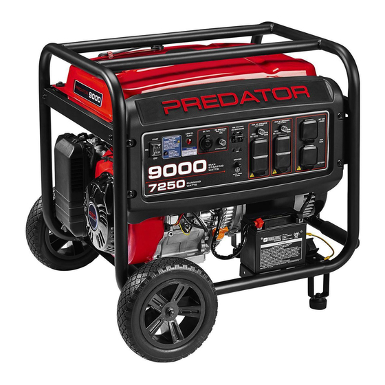
9000 WATT
PORTABLE
GENERATOR
7250 RUNNING WATTS
9000 MAX STARTING WATTS
Using a generator indoors CAN
KILL YOU IN MINUTES.
Generator exhaust contains
carbon monoxide. This is a poison
you cannot see or smell.
NEVER use inside
a home or garage,
EVEN IF doors and
windows are open.
When unpacking, make sure that the product is intact
and undamaged. If any parts are missing or broken,
please call 1-888-866-5797 as soon as possible.
©
Copyright
2022 by Harbor Freight Tools
No portion of this manual or any artwork contained herein may be reproduced in
any shape or form without the express written consent of Harbor Freight Tools.
Diagrams within this manual may not be drawn proportionally. Due to continuing
improvements, actual product may differ slightly from the product described herein.
Tools required for assembly and service may not be included.
Keep this manual for the safety warnings and precautions, assembly,
Visit our website at: http://www.harborfreight.com
Email our technical support at: productsupport@harborfreight.com
Email our engine support at: predator@harborfreight.com
Only use OUTSIDE
and far away from
windows, doors,
and vents.
®
. All rights reserved.
Do not use in
trailers, truck
beds, or tents.
Read this material before using this product.
Failure to do so can result in serious injury.
SAVE THIS MANUAL.
DANGER
Use at least 20 feet away from
people, animals, and structures
with exhaust pointed away.
20'
20'
20'
22f
59134
20'
20'
Advertisement
Table of Contents

Related Manuals for Predator 9000


Summary of Contents for Predator 9000
- Page 1 7250 RUNNING WATTS 9000 MAX STARTING WATTS Visit our website at: http://www.harborfreight.com Email our technical support at: productsupport@harborfreight.com 59134 Email our engine support at: predator@harborfreight.com DANGER Do not use in Use at least 20 feet away from Using a generator indoors CAN...
-
Page 2: Important Safety Instructions
Table of Contents Safety ............2 Maintenance ..........18 Specifications ..........7 Parts List and Diagram ......26 Setup ............9 Warranty ............ 30 Operation ........... 11 WARNING SYMBOLS AND DEFINITIONS This is the safety alert symbol. It is used to alert you to potential personal injury hazards. -
Page 3: Operating Precautions
Set up precautions (continued) 10. Use only lubricants and fuel 12. Do not operate the Generator before grounding. recommended in this manual. The Generator must be earth-grounded in accordance with all relevant electrical 11. Improper connections to a building electrical system codes and standards before operation. - Page 4 10. Fire Hazard! Do not fill gas tank while engine is 19. Insulate all connections and disconnected wires. running. Do not operate if gasoline has been spilled. 20. Guard against electric shock. Prevent body Clean spilled gasoline before starting engine. contact with grounded surfaces such as Do not operate near pilot light or open flame.
- Page 5 35. Keep the Generator, its engine, and 41. Before use, check for misalignment or binding surrounding area clean at all times. of moving parts, breakage of parts, and any other condition that may affect the Generator’s 36. Do not smoke, or allow sparks, flames, operation.
-
Page 6: Service Precautions
Service precautions 1. Before service, maintenance, or cleaning: GFCI protection: a. Unplug all devices from the Generator. This Generator is equipped with two 3-Prong, b. Turn the engine switch to its “OFF” position. duplex 120 V ground fault circuit interrupter (GFCI) receptacles. -
Page 7: Specifications
Functional Description Specifications 120 / 2 40 V AC, 60 H z Output 60.4A at 120V; 30.2A at 240V 7,250 Running Watts (9,000 Max. Starting Watts) Battery needed for electric start 12 V , lead acid, 9Ah Minimum Generator (not included) Two 3-Prong, duplex NEMA #5-20 120 ... - Page 8 Components and Controls (continued) The following are descriptions of the controls on the power panel. Your Generator has sockets to power your products with circuit breakers to protect the voltage flow. 3. Circuit Breakers: The circuit breaker protects the Generator from overloading. The rating of the START breaker and the load it protects are marked near the breaker.
- Page 9 Initial Tool Set Up/Assembly Read the ENTIRE IMpORTANT SAFETY INFORMATION section at the beginning of this manual including all text under subheadings therein before set up or use of this product. TO pREVENT SERIOUS INJURY: Operate only with proper spark arrestor installed. Operation of this equipment may create sparks that NOTICE: This Generator is not intended to power can start fires around dry vegetation.
- Page 10 Grounding The Generator must be properly grounded in 1. Drive electrode at least 8 ft. accordance with all relevant electrical codes and vertically into the ground. standards before operation. In many locations, local a. If rock layer prevents vertical entry, drive at an code will not require this generator to be grounded angle not exceeding 45 degrees from vertical.
-
Page 11: Carburetor Assembly
High Altitude Operation Above 3000 feet WARNING! TO pREVENT SERIOUS INJURY FROM FIRE: Follow instructions in a well-ventilated area away from ignition sources. If the engine is hot from use, shut the engine off and wait for it to cool before proceeding. Do not smoke. NOTICE: Warranty void if necessary adjustments are not made for high altitude use. - Page 12 Operating Instructions Read the ENTIRE IMpORTANT SAFETY INFORMATION section at the beginning of this manual including all text under subheadings therein before set up or use of this product. Inspect tool before use, looking for damaged, loose, and missing parts. If any problems are found, do not use tool until repaired.
-
Page 13: Using The Generator
Using the Generator Before Starting the Generator Engine 4. Plug in products. Before starting the engine: 5. When finished using the Generator, disconnect all electrical loads. a. Follow the Set Up Instructions to prepare the Generator. Note: Do not allow Generator to run b. -
Page 14: Starting The Engine
Starting the Engine 1. To start a cold engine, move the Choke to the START position. To restart a warm engine, leave the Choke in the RUN position. 2. Open the Fuel Valve. For MANUAL START For ELECTRIC START A. Turn the Engine Switch to ON. Turn the Engine Switch to START. -
Page 15: Connecting Electrical Loads
CARBON MONOXIDE SHUTOFF DANGER! TO pREVENT SERIOUS INJURY AND DEATH FROM CARBON MONOXIDE INHALATION: The Carbon Monoxide sensor is an additional layer of protection only. Do not use the Generator in any area or situation that will allow carbon monoxide to accumulate. •... - Page 16 Calculating Total Wattage of Devices Used with the Generator Before using the Generator, check that the products Wattage Estimate Charts you want to plug into the unit are below the rated and Note: Wattages listed below are estimates for that maximum wattage ratings of the Generator.
-
Page 17: Stopping The Engine In An Emergency
Stopping the Engine in an Emergency 1. To stop the engine in an emergency, turn the Engine Switch off. START NOTICE: Generator shut-off under load may damage the Generator and attached equipment. Stopping the Engine Under Normal Conditions 1. Before turning off the Engine, turn off all electrical loads, RESET then unplug them. -
Page 18: Cleaning, Maintenance, And Lubrication
User-Maintenance Instructions procedures not specifically explained in this manual must be performed only by a qualified technician. TO pREVENT SERIOUS INJURY FROM ACCIDENTAL OpERATION: Turn the power Switch of the Generator to its “OFF” position, wait for the engine to cool, and disconnect the spark plug cap before performing any inspection, maintenance, or cleaning procedures. -
Page 19: Checking And Filling Fuel
Checking and Filling Fuel Note: Do not use gasoline that has been stored in a WARNING! TO pREVENT SERIOUS metal fuel container or a dirty fuel container. It can INJURY FROM FIRE: cause particles to enter the carburetor, effecting Fill tank in a well-ventilated area away engine performance and/or causing damage. -
Page 20: Spark Plug Maintenance
Spark plug Maintenance 1. Disconnect spark plug cap from end of plug. 4. When installing a new spark plug, adjust Clean out debris from around spark plug. the plug’s gap to the specification on the Specifications chart. Do not pry against the 2. - Page 21 4. STORAGE AREA: 6. AFTER STORAGE: Cover and store in a dry, level, well-ventilated Before starting the Engine during or after area out of reach of children. Storage area should storage, keep in mind that untreated gasoline also be away from ignition sources, such as will deteriorate quickly.
-
Page 22: Troubleshooting
Troubleshooting problem possible Causes probable Solutions Engine will not start FUEL RELATED: FUEL RELATED: 1. No fuel in tank or fuel valve closed. 1. Fill fuel tank with fresh 87+ octane stabilizer treated unleaded gasoline and open fuel valve. Do not use gasoline with more than 10% ethanol (E15, E20, E85, etc.). - Page 23 Troubleshooting (continued) problem possible Causes probable Solutions Engine stops when 1. Dirty air filter. 1. Clean or replace element. under heavy load 2. Engine running cold. 2. Allow engine to warm up prior to operating equipment. Engine misfires 1. Spark plug cap loose. 1.
- Page 24 Troubleshooting (continued) problem possible Causes probable Solutions Product doesn’t 1. Product not plugged in properly. 1. Turn off and unplug the product, then have power. plug it back in again and turn on. 2. Circuit Breaker tripped. 2. Turn off and unplug product. Reset Circuit Breaker.
-
Page 25: Please Read The Following Carefully
pLEASE READ THE FOLLOWING CAREFULLY THE MANUFACTURER AND/OR DISTRIBUTOR HAS PROVIDED THE PARTS LIST AND ASSEMBLY DIAGRAM IN THIS MANUAL AS A REFERENCE TOOL ONLY. NEITHER THE MANUFACTURER OR DISTRIBUTOR MAKES ANY REPRESENTATION OR WARRANTY OF ANY KIND TO THE BUYER THAT HE OR SHE IS QUALIFIED TO MAKE ANY REPAIRS TO THE PRODUCT, OR THAT HE OR SHE IS QUALIFIED TO REPLACE ANY PARTS OF THE PRODUCT. -
Page 26: Parts List
parts List and Diagram parts List part Description part Description Flanged Hex Bolt Flanged Hex Bolt Flat Washer Fuel Level Gauge Power Socket Assembly Phillips Countersunk Head Screw Weather Proof Cover Clamp Panel Output Indicator Light Tank Cover Start Control Switch Filter Screen Weather Proof Cover Tank... - Page 27 parts List (continued) part Description part Description Throttle Return Spring Push Rod Throttle Rod Crankcase Body Valve Adjustment Cap Oil Seal Valve Locker Flat Washer Valve Spring Retainer Speed Regulating Arm Valve Inner Spring Pin Clip Valve Oil Seal Speed Regulating Bracket Valve Spring Seat Starter Motor Assembly Valve Kit...
-
Page 28: Assembly Diagram
Assembly Diagram 1 Page 28 For technical questions, please call 1-888-866-5797. ITEM 59134... - Page 29 Assembly Diagram 2 ITEM 59134 For technical questions, please call 1-888-866-5797. Page 29...
-
Page 30: Emissions Control System Warranty
Warranties Limited 90 Day Warranty (Retail) Harbor Freight Tools Co. makes every effort to assure that its products meet high quality and durability standards, and warrants to the original purchaser that this product is free from defects in materials and workmanship for the period of 90 days from the date of purchase. -
Page 31: General Emissions Warranty Coverage
GENERAL EMISSIONS WARRANTY COVERAGE a) The warranty period begins on the date the engine or equipment is delivered to an ultimate purchaser. The warranty period is two years. b) HFT warrants to the initial owner and each subsequent owner that the engine is: 1. - Page 32 26677 Agoura Road • Calabasas, CA 91302 • 1-888-866-5797...
Need help?
Do you have a question about the 9000 and is the answer not in the manual?
Questions and answers
How many from amps on the predater 9000
The Predator 9000 generator features the following AC outlet amp ratings:
- Two Duplex 120V 20A (5-20R) GFCI outlets
- 120V 30A (L5-30R) receptacle
- 120/240V 30A (L14-30R) receptacle
It also has one DC outlet rated at 12V 10A.
This answer is automatically generated