
Subscribe to Our Youtube Channel
Related Manuals for THORLABS MX10C Series

Summary of Contents for THORLABS MX10C Series
- Page 1 MX10C Series 12.5 Gb/s Optical Transmitters MX40C Series 40 Gb/s Optical Transmitters User Guide...
-
Page 3: Table Of Contents
4.6.2 System Information Page ........................20 4.6.3 Accent LED Settings Page ........................ 20 4.6.4 Thorlabs Help Page .......................... 21 Chapter 5 Specifications ................................. 22 General System Specifications ........................22 Power and Environmental Specifications ....................23 Internal Control Specifications ........................23 Internal Amplifier Specifications ........................ - Page 4 MX10C, MX40C Series of Optical Transmitters Replacing the Main Fuse ..........................30 Chapter 9 Troubleshooting ..............................31 Chapter 10 Declarations of Conformity ......................... 32 Chapter 11 Thorlabs Worldwide Contacts ........................34...
-
Page 5: Chapter 1 Introduction
RF amplifiers is user-adjustable. Variable optical attenuators (VOAs) and power monitors enable completely automatic optical output power control and stabilization. The MX10C series includes an external loop-back cable for the driver RF output and modulator RF input ports, which provides the opportunity to use an external driver, if desired. -
Page 6: Block Diagram
The Laser In port uses PM fiber with light linearly polarized along the slow axis as shown on the front panel. Maximum input power is 20 dBm (100 mW). In the MX10C series, the user also has the option of using their own modulator driver connected to the Modulator RF In port. -
Page 7: Front And Back Panel Overview
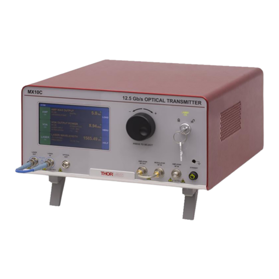
MX10C, MX40C Series of Optical Transmitters Chapter 1: Introduction 1.4 Front and Back Panel Overview Figure 2 Front Panel Callout Description MX10C Series MX40C Series Touchscreen Display Adjustment Knob Key Switch and Indicator Lasing Disabled; Lasing Enabled Grounding Jack (Banana... - Page 8 MX10C, MX40C Series of Optical Transmitters Chapter 1: Introduction Figure 3 Back Panel Callout Description MX10C Series MX40C Series I/O Port DB-15 DB-15 Option Label RS-232 Port DB-9 DB-9 USB Port, Type B Laser Interlock 2.5 mm 2.5 mm Power Connector...
-
Page 9: Chapter 2 Safety
If equipment is used in a manner not specified by the manufacturer, the protection provided by the equipment may be impaired. Only with written consent from Thorlabs may changes to single components be carried out or components not supplied by Thorlabs be used. -
Page 10: Precautions
3 meters (9.8 feet). Thorlabs is not responsible for any radio television interference caused by modifications of this equipment or the substitution or attachment of connecting cables and equipment other than those specified by Thorlabs. The correction of interference caused by such unauthorized modification, substitution or attachment will be the responsibility of the user. -
Page 11: Chapter 3 Quick Start Guide
PM Loopback Fiber Cable Installed Figure 7 Amplifier RF Out present only on the MX10C series. This cable is not installed on the MX40C series. Insert the key into the interlock switch and turn it towards the unlock symbol ( ). -
Page 12: Controls On The Home Page
MX10C, MX40C Series of Optical Transmitters Chapter 3: Quick Start Guide 3.2 Controls on the Home Page The MX10C and MX40C series of transmitters can be fully controlled by using the resistive touchscreen display for all functions. The screen is sensitive to the touch of a finger or a plastic stylus, and selections are made by tapping the on-screen button of interest. -
Page 13: System Wavelength Setting
MX10C, MX40C Series of Optical Transmitters Chapter 3: Quick Start Guide System Wavelength Setting The operational wavelength range of the MX10C and MX40C series extends from 1250 nm to 1610 nm. The three calibration wavelengths of the power monitors, 1310 nm, 1550 nm, and 1590 nm, represent the centers of the O-band, C-band, and L-band and provide the user with accurate power readings at or near those wavelengths. -
Page 14: Controls On The Settings
MX10C, MX40C Series of Optical Transmitters Chapter 3: Quick Start Guide 3.4 Controls on the Settings Pages The Settings pages all follow the same general design and functionality as shown in the example screen shot below. The upper section with white letters displays the parameters that can be changed. Simply tap on the parameter of interest to highlight it, and the controls for that parameter will be presented. -
Page 15: Quick Start
MX10C, MX40C Series of Optical Transmitters Chapter 3: Quick Start Guide Quick Start The following steps summarize the setup procedure required to operate the MX10C and MX40C series in the standard mode. Please refer to previous sections in this chapter and the expanded operating instructions in Chapter 4 for additional information. Turn on power to the MX10C or MX40C series transmitter via the power switch on the back panel (Figure 4). -
Page 16: Chapter 4 Operating Instructions
MX10C, MX40C Series of Optical Transmitters Chapter 4: Operating Instructions Chapter 4 Operating Instructions 4.1 Control Loop Diagram The following diagram shows the control loops added to the block diagram. From this picture, the user can see how the power monitors and VOA are used to provide stability and control to the whole system. - Page 17 MX10C, MX40C Series of Optical Transmitters Chapter 4: Operating Instructions Tap here to adjust crossing set point from -100 to +100. Tap here to optimize output swing. Tap here to adjust maximum output swing in Digital mode. Figure 17 Digital Amplifier Mode Settings The Max Output Swing field allows the user to set the peak-to-peak output voltage of the amplifier, assuming the amplifier input signal is large enough to cause the amplifier to start clipping.
- Page 18 MX10C, MX40C Series of Optical Transmitters Chapter 4: Operating Instructions In the Analog mode, the Max Output Swing is locked at the maximum set point of 7.0 V , so the amplifier can drive the modulator linearly with minimal distortion. However, in order to do this, the user must supply a signal with small enough amplitude so the amplifier does not saturate, or clip.
-
Page 19: Variable Optical Attenuator Settings Page
MX10C, MX40C Series of Optical Transmitters Chapter 4: Operating Instructions 4.3 Variable Optical Attenuator Settings Page To get to the Variable Optical Attenuator (VOA) Settings page, tap in the VOA monitors pane on the Home page. The VOA provides the means for adjusting and stabilizing the output power after the modulator. Note that the power measurement units for the entire interface are set on this page. -
Page 20: Laser Settings Page
MX10C, MX40C Series of Optical Transmitters Chapter 4: Operating Instructions Laser Settings Page To access the Laser Settings page, tap on the Laser monitors pane on the Home page. Here the user can control the laser wavelength and choose whether or not to use the dither feature to stabilize the wavelength. Turning the dither off will result in lower phase and intensity noise, but the wavelength may drift slightly over time. - Page 21 MX10C, MX40C Series of Optical Transmitters Chapter 4: Operating Instructions In "STEP 1GHz" mode you can edit the fine-tuning frequency offset in steps of 1 GHz. Figure 25 Changing the Fine-Tuning Step Size Note that while the L-band and C-band lasers can have their frequency adjusted by increments as small as 1 MHz, the laser’s actual tuning accuracy is not this fine.
-
Page 22: Load Page
MX10C, MX40C Series of Optical Transmitters Chapter 4: Operating Instructions 4.5 Load Page To get to this page, tap the blue Load button on the Home page. The Load page allows the user to revert back to the factory default settings. Future firmware revisions will have the ability to store and load instrument states defined by the user. Tap to restore factory settings. -
Page 23: Menu Page
LEDs producing the light emanating from the bottom of the instrument. Tap here to find help from Thorlabs Technical Support. Figure 30 Controls on the Menu Page 4.6.1 Display and Sound Settings Page To open the screen shown below, tap the DISPLAY AND SOUNDS button on the Menu pane. -
Page 24: System Information Page
MX10C, MX40C Series of Optical Transmitters Chapter 4: Operating Instructions 4.6.2 System Information Page To open the screen shown below, tap the SYSTEM INFORMATION button on the Menu pane. The System Information page displays the installed hardware and software versions. This is useful information when in need for tech-support or to verify firmware revisions. -
Page 25: Thorlabs Help Page
To open the screen shown below, tap the THORLABS HELP button on the Menu pane. The Thorlabs Help page displays the Tech Support phone number, Thorlabs web site, and the installed hardware and software versions. This information will be useful when speaking with Tech Support. -
Page 26: Chapter 5 Specifications
MX40C Series 7.0 dB (1310 nm) An 850 nm fixed-wavelength laser can be substituted upon request: contact Thorlabs’ technical support. Using the modulator at another wavelength (e.g. visible light) may cause an increase in insertion loss and will void the warranty. -
Page 27: Power And Environmental Specifications
Per Monitor VOA Insertion Loss 0.4 dB Typical VOA Response Time 5.4 Internal Amplifier Specifications Parameter Typical Values Notes MX10C Series 35 ps Rise/Fall Time Large Signal, Digital Response MX40C Series 8 ps MX10C Series 34 dB RF Amplifier Gain... -
Page 28: Laser Specifications
MX10C, MX40C Series of Optical Transmitters Chapter 5: Specifications 5.6 Laser Specifications Parameter Unit Typ. C-Band Tunable Laser (MX10C, MX40C) Optical Output Power 12.5 13.5 14.5 Frequency Range 191.50 196.25 Wavelength Range 1527.6 1565.5 Frequency Accuracy -1.5 Tuning Resolution Tuning Speed (Between Wavelengths) Fine Tuning Resolution Fine Tuning Speed GHz/s... -
Page 29: Chapter 6 Control And Pc Connections
Item # into the search field. The instrument’s firmware can be updated by uploading the new version from a PC via the USB port. Thorlabs’ technical support can provide up-to-date information on available firmware revisions and control functions. -
Page 30: The Laser Safety Interlock
If the switch returns to a closed condition the laser source must be turned on again in the touchscreen GUI. All units shipped from Thorlabs are configured with a shorting device installed in the Interlock connector. If you are not going to use this feature, then leave the shorting device installed. -
Page 31: Chapter 7 Mechanical Drawings
MX10C, MX40C Series of Optical Transmitters Chapter 7: Mechanical Drawings Chapter 7 Mechanical Drawings 7.1 MX10C Series Figure 4 Mechanical Drawing of the MX10C Series Rev. F, February 21, 2020 Page 27... -
Page 32: Mx40C Series
MX10C, MX40C Series of Optical Transmitters Chapter 7: Mechanical Drawings 7.2 MX40C Series Figure 5 Mechanical Drawing of the MX40C Series Page 28 TTN048898-D02... -
Page 33: Chapter 8 Maintenance, Repair, And Fuses
Fiber End-Face Cleaner for Patch Cords The optical connectors on the front panel may be cleaned using a 2.5 mm bulkhead cleaner such as the Thorlabs FBC250. This allows the user to clean the fiber end-face without removing it from the internal bulkhead adapter. -
Page 34: Replacing The Main Fuse
Investigate the fuse. This can be done with a simple continuity check. If in doubt, replace the fuse. A spare fuse is stored in the fuse holder. Additional replacement fuses can be purchased from Thorlabs. Always use fuses of the same type as the original. -
Page 35: Chapter 9 Troubleshooting
Below is some information about status indicators and a few checks to help in troubleshooting general problems. If you have any questions, please contact your local Thorlabs Technical Support office. If the unit does not appear to turn on correctly, please check the following items: ... -
Page 36: Chapter 10 Declarations Of Conformity
MX10C, MX40C Series of Optical Transmitters Chapter 10: Declarations of Conformity Chapter 10 Declarations of Conformity Page 32 TTN048898-D02... - Page 37 MX10C, MX40C Series of Optical Transmitters Chapter 10: Declarations of Conformity Rev. F, February 21, 2020 Page 33...
-
Page 38: Chapter 11 Thorlabs Worldwide Contacts
Contact Thorlabs for more information. Waste treatment is your own responsibility. “End of life” units must be returned to Thorlabs or handed to a company specializing in waste recovery. Do not dispose of the unit in a litter bin or at a public waste disposal site. - Page 40 www.thorlabs.com...
Need help?
Do you have a question about the MX10C Series and is the answer not in the manual?
Questions and answers