Table of Contents
Advertisement
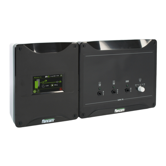
Quick Links
Advertisement
Table of Contents

Related Manuals for Fancom AURA 70


Summary of Contents for Fancom AURA 70
- Page 2 N.B.: The original, authentic version of this manual is the English version produced by Fancom B.V. or one of its daughter companies (referred to further as Fancom). Any modifications introduced to this manual by third parties have neither been checked nor approved by Fancom. Modifications are taken by Fancom to include translations into languages other than English and the insertion and/or deletion of text and/or illustrations to/from the original contents.
-
Page 3: Table Of Contents
Fancom Sales & Service Center ..................... 1 Safety instructions and warnings ....................2 Aura 70 ................................ 3 Basic principles of the Aura 70 ....................... 3 Schematic view for positioning the components ................4 Example time schedule........................4 Using the Aura 70 ............................6 Main parts ............................ -
Page 4: Fancom Sales & Service Center
Decimals The control computer and this manual use a decimal point in values. For example: a weight is shown as 1.5 kg (not as 1,5 kg). For any questions and support, please contact the local Fancom Sales & Service Center. - Page 5 The guarantee does not apply if this product is installed in any other way than is indicated by Fancom and if the product's motor has been opened and changes have been made to the product.
-
Page 6: Aura 70
Feeding of groups of rearers or fatteners using liquid and dry feed troughs is possible. The Aura 70 has a built-in time clock. The feed system is started externally or automatically at preset times. The Aura 70 enables to choose whether you will start: ... -
Page 7: Schematic View For Positioning The Components
Aura 70 Aura 70 Figure 2: Schematic view for positioning the components When the option ‘Filling the dispensers’ is chosen, the circuit will be filled first (circuit filling). This method is usually used with dry or liquid feed troughs but there are also situations using a combination with dispensers. The chain will start first to dose the feed into the dispensers. - Page 8 Aura 70 Aura 70 When the option ‘Start with dosator’ is chosen, the dispensers will open and the feed will fall into the troughs (Dispenser run time). During the settable wait time sections can be inspected and dispensers can be adjusted per animal.
-
Page 9: Using The Aura 70
Aura 70 Using the Aura 70 This chapter describes the main parts and the operation of the Aura 70. The Aura 70 can be operated on the touch screen. Touch screen Silo 1 control switch Silo 2 control switch Circuit control switch (automatically switch off in case of a chain break) Dosator control switch The computer is automatically activated as soon as you switch on the power. - Page 10 Aura 70 Using the Aura 70 The Aura 70 screens are divided in three sections: Title bar: Displays the date and time and provides access to the installation and user menu. Working area: Displays the data user or installation settings of the control computer.
-
Page 11: User Settings
Aura 70 User settings Silo Auger: If the silo auger is active the auger will light up green. Silo’s: If more than one silo is used the silo number will appear in the icon. Silo switch over sensor: If a silo is empty (sensor detects no feed) the system switch over to the other silo (only if more than one silo is used). - Page 12 Aura 70 User settings Not available. Readout of the circuit number. Readout of the run time of today. Readout of the run time of yesterday. Readout of the run time of the day before yesterday. Readout of the total run time.
-
Page 13: Alarm
Aura 70 Alarm The Aura 70 displays the alarm overview by pressing . There are two types of alarm: Loud alarm: An active loud alarm sounds a siren, shows an alarm message and a report on the screen. This type of alarm has a high priority. - Page 14 Proces alarms Alarm Action Thermal alarm Check the thermal security in the Aura 70. Process blocked System and new start time ranges are still blocked. Start the system (push button). Chain is broken No pulses or input cable break. Check the cable machine.
-
Page 15: Alarm Overview
The alarm message states that the alarm has been disabled and is active again. The message will be cleared from the alarm overview. Fancom advises testing the alarm weekly for correct functioning. During the test the control computer will give a loud alarm. - Page 16 Aura 70 Alarm Max. runtime circuit Setting of the maximum runtime (hours:minutes). One setting for all circuits. The control computer stores the alarm history. The computer stores the last six alarm messages.
-
Page 17: Installing The Aura 70
Never mount the Aura 70 in a humid and/or dusty room and certainly not in the room where the animals are present. Mount the Aura 70 at such a height that you can control the Aura 70 easily (eye level) and square on a solid backing. The swivels should be positioned at the bottom. - Page 18 Check that the mains voltage and frequency, for which this computer is suitable, correspond to the mains voltage and frequency on site. Be sure that the Aura 70 is properly grounded. When using metal cable trays, grounding at one point of the tray is recommended.
- Page 19 Control computers 2 and 3 are looped. These looped control computers do not require a terminal resistor. The Fancom Greenlink cable (UTP 1x2x0.8mm, unshielded twisted pair) used to wire the FNET and I/O net. Maximum cable length = 1200 meters.
-
Page 20: Installer Settings
Aura 70 Installer settings Version Readout of the software version number of the Aura 70. Computer number Setting of the unique computer number. If the computer is part of Fnet (FNET) communication, it must have its own, unique number (like all the other connected computers). - Page 21 Installer settings Communciation FNet is the Fancom Network. Several control computers can be linked via this network. FNet is also used to operate the connected control computers from a PC. Master-Slave Master/Slave setting. If the control computer is included in a network, only one control computer in the network must be set as MASTER.
- Page 22 Aura 70 Installer settings Auger silo 1-2 Setting of the input address of the auger silo Rel.3 / Rel.4). Return feed sensor Setting of the input address of the return feed sensor / AI.3). Return feed delay (sec) Setting of the delay time (seconds) before the return feed sensor is active. During this time this sensor is ignored.
-
Page 23: Sys
Aura 70 Installer settings System full sensor Setting of the input address of the system full sensor / AI.1). System full delay (min) Setting of the delay time (minutes) before the system full sensor is active. During this time this sensor is ignored. -
Page 24: Technical Specifications Aura 70 + Switchbox
Relay 1-4, voltage free* Max. 2A 60Vdc/30Vac Alarm relay, voltage free* Max. 2A 60Vdc/30Vac 3 analog outputs Voltage range 0-10Vdc Maximum load 570Ω Output resistance 1 DSR-input Max. frequency 200 Hz Communication Fancom FNet for inter-communication of computers and PC connection PC*. -
Page 25: Aura Board
Aura 70 Technical specifications Aura 70 + Switchbox Aura board Powerboard FCA Silo switch 1 Silo switch 2 Chain switch (with softstarter optional) - Page 26 Aura 70 Technical specifications Aura 70 + Switchbox IO Net - IO Net + Fnet 1- Fnet 1+ Fnet 2- Fnet 2+ SD Card AI1: System full sensor AI2: Dosator close input / external start AI3: Return feed sensor AI4: Silo switch over sensor...
- Page 27 Aura 70 Technical specifications Aura 70 + Switchbox Standard (L1, L2, L3) 1-2 Chain break (NC) 3-4 Chain drive safety switch on cover (NC) 5 Dosator motor (240V) N 6 Dosator motor (240V) Open 7 Dosator motor (240V) Close N Power supply...
- Page 28 Aura 70 Technical specifications Aura 70 + Switchbox Standard (L1, L2, L3) Silo 1 auger motor Silo 2 auger motor Chain drive motor or chain drive motor with softstarter US Variant Silo 1 auger motor Silo 2 auger motor Chain drive motor or...
-
Page 29: Appendix: Eg-Declaration Of Compliance
Aura 70 Appendix: EG-declaration of compliance Manufacturer Fancom B.V. Address: Industrieterrein 34 Place: Panningen (the Netherlands) Hereby declares that: Aura 70 Satisfies the conditions of: The Low Voltage Directive 2014/35/EU according to EN-61010 the EMC Guideline, directive 2014/30/EU Emission and immunity according to NEN-EN-IEC 61326...
Need help?
Do you have a question about the AURA 70 and is the answer not in the manual?
Questions and answers