Table of Contents
Advertisement
Quick Links
Advertisement
Table of Contents

Related Manuals for Osram AS5045B


Summary of Contents for Osram AS5045B
- Page 1 Product Document Published by ams OSRAM Group...
- Page 2 User Manual – AS5045B-AB-v1.0 AS5045B 12-bit Rotary Position Sensor with Digital Angle (Interface), PWM and ABI output www.ams.com Revision 1.1 / 05.07.2013 page 1/15...
-
Page 3: Table Of Contents
Standalone incremental Output ..................11 Daisy chain mode ....................... 12 Programming the AS5045B ....................13 AS5045B-AB-Hardware ..................... 14 AS5045B-AB-1.0 Schematics .................... 14 AS5045B – AB – 1.0 PCB layout ..................14 Copyright ..........................15 Disclaimer .......................... 15 Contact Information ......................15 Revision History... -
Page 4: General Description
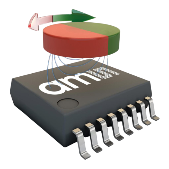
Figure 1: Rotary Position Sensor AS5045B + Magnet The AS5045B adapter board The AS5045B adapter board is a simple circuit allowing test and evaluation of the AS5045B rotary position sensor quickly without building a test fixture or PCB. 2.1 Board description The PCB can be used as standalone unit or attached to a microcontroller. -
Page 5: Mounting The As5045B Adapter Board
2.2 Mounting the AS5045B adapter board A diametric magnet must be placed over on under the AS5045B encoder, and should be centered on the middle of the package with a tolerance of 0.5mm. The airgap between the magnet and the encoder casing should be maintained in the range 0.5mm~2mm. - Page 6 User Manual – AS5045B-AB Figure 3: AS5045B – AB - mounting and dimension Magnet 0.5~2mm AS5045B 22mm PWM Ind 3V3 CSn CLK 4x2.6mm Diametral Magnet AS5045B 18mm www.ams.com Revision 1.1 / 05.07.2013 page 5/15...
-
Page 7: As5045B Adapter Board And Pinout
User Manual – AS5045B-AB AS5045B adapter board and pinout Figure 4: AS5045B adapter board connectors and encoder pinout PWM Ind 3V3 CSn CLK AS5045B-AB-1.0 AS5040 Table 1: Pin description Pin# Pin# Symbol Type Description Board AS5040 Board JP1 - 1... - Page 8 User Manual – AS5045B-AB Pin# Pin# Symbol Type Description Board AS5040 Board AS5040 – AS5140 – AS5145 (programmed) only Mode1.x: Quadrature B channel quarter period shift to channel A. JP2 - 5 Mode2.x: Direction of Rotation Mode3.x: V signal (phase2) AS5040 –...
-
Page 9: Operation Cases
The most complete and accurate solution for a MCU to read the angle of a magnet is the serial interface. 4.1 Standalone SSI output mode The serial word contains 12 bits for AS5045B angle value and some other indicator bits like MagINC, MagDEC, which can be read at the same time. Figure 5:... -
Page 10: Standalone Pwm Output Mode
4.2 Standalone PWM output mode The AS5045B provides a pulse width modulated output (PWM), whose duty cycle is proportional to the measured angle. The PWM signal (J2 pin #7) with a period of 1025us (1us step) and 5V pulse voltage can be connected to the capture/timer input of a microcontroller in order to decode the angle value. - Page 11 User Manual – AS5045B-AB Figure 7: PWM duty cycle depending on magnet position Angle 0 deg (Pos 0) 1µs 1025µs 359.65 deg (Pos 1023) 1024µs www.ams.com Revision 1.1 / 05.07.2013 page 10/15...
-
Page 12: Standalone Incremental Output
Three different incremental output modes are possible with quadrature A/B being the default mode (two-channel quadrature, step / direction incremental signal (LSB) and the direction bit in clockwise (CW) and counter-clockwise (CCW) direction. The pre-programmed version AS5045B provides a 12bit incremental output. Figure 8: Using the Incremental output with the adapter board... -
Page 13: Daisy Chain Mode
User Manual – AS5045B-AB 4.4 Daisy chain mode By using more than one adapter board, a setup in daisy chain mode is possible. Note: In this mode capacitor C3 (Fig.12) must be disconnected when using the 1nF capacitor shown in Fig.9. or directly replaced by this capacitor. -
Page 14: Programming The As5045B
CLK = low. 16 bit configuration data must be serially shifted into the OTP register via the Prog-pin. The first “CCW” bit is followed by the zero position data (MSB first - 12 bit for AS5045B) and some mode settings (please refer to datasheet). Data must be valid at the rising edge of CLK. -
Page 15: As5045B-Ab-Hardware
10u/10V PWM_LSB Index Index_W 3.3V PROG PROG Prog AS5045B Header 7 100n 6.2 AS5045B – AB – 1.0 PCB layout Figure 12: AS5045B-AB-1.0 adapter board layout Size Project Title ProjTitle Date ProjDate Originator Originator www.ams.com Revision 1.1 / 05.07.2013 page 14/15... -
Page 16: Copyright
User Manual – AS5045B-AB Copyright Copyright ams AG, Tobelbader Strasse 30, 8141 Unterpremstätten, Austria-Europe. Trademarks Registered. All rights reserved. The material herein may not be reproduced, adapted, merged, translated, stored, or used without the prior written consent of the copyright owner.
Need help?
Do you have a question about the AS5045B and is the answer not in the manual?
Questions and answers