Advertisement
Quick Links
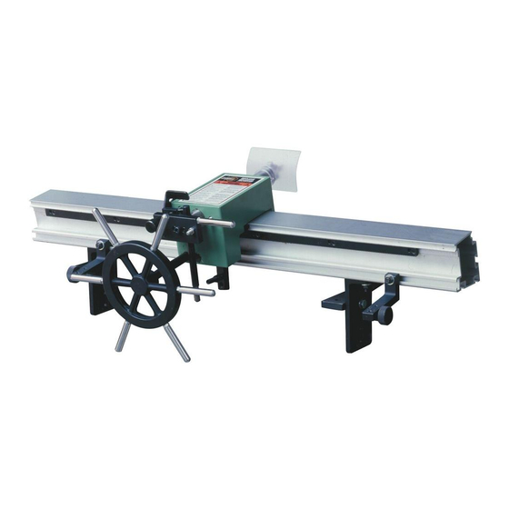
FEATURES
Designed for rough bulk material
removal from wood blanks, to make
multiple matching spindles that follow the
profile of an original spindle or a shop
made template.
Extruded aluminum base and carriage.
Smooth hand wheel controlled rack &
pinion system.
High speed steel cutter.
Fits most 12" - 22" floor model lathes with
cast bedways.
* Some manual shaping of fine details and fin-
ish sanding will still be required.
SPECIFICATIONS
MAXIMUM DUPLICATING LENGTH
36" (914 mm)
MAXIMUM DUPLICATING DIAMETER
2"~20" (51 ~ 508 mm)
Depending on lathe swing over bed
MAXIMUM DUPLICATING DEPTH
3" (76 mm)
MAXIMUM ORIGINAL SPINDLE DIAMETER
5" (127 mm)
MAXIMUM WIDTH OF TEMPLATE
3" (76 mm)
DUPLICATES FROM
ORIGINAL SPINDLE OR TEMPLATE
MAXIMUM DEPTH OF CUT PER PASS
1/4" (6.35 mm) -
1/8" recommended
REVISION 3 - JANUARY 13/11
© Copyright General® International 01/2011
LATHE NOT INCLUDED
Advertisement

Subscribe to Our Youtube Channel
Summary of Contents for General International 25-036
- Page 1 FEATURES Designed for rough bulk material removal from wood blanks, to make multiple matching spindles that follow the profile of an original spindle or a shop made template. Extruded aluminum base and carriage. Smooth hand wheel controlled rack & pinion system. High speed steel cutter.
- Page 2 THANK YOU for choosing this General ® International model 25-036 Wood Lathe Duplicator. This duplicator has been carefully tested and inspected before shipment and if properly used and maintained, will provide you with years of reliable service. For your safety,...
- Page 3 ® ® GENERAL & GENERAL INTERNATIONAL WARRANTY All component parts of General®, General® International and Excalibur by General International ® products are carefully inspected during all stages of production and each unit is thoroughly inspected upon completion of assembly. Limited Lifetime Warranty Because of our commitment to quality and customer satisfaction, General®...
-
Page 4: Rules For Safe Operation
RULES FOR SAFE OPERATION To help ensure safe operation, please take a moment to learn the machine’s applications and limitations, as well as poten- tial hazards. General® International disclaims any real or implied warranty and holds itself harmless for any injury that may result from improper use of its equipment. -
Page 5: Basic Functions
BASIC FUNCTIONS This General International model 25-036 wood lathe duplicator is designed for use on wood lathes only. Installation and/or use on Metalworking lathes or any other machinery can lead to serious personal injury, damage to the machine, the duplicator and the workpiece. - Page 6 ASSEMBLING & INSTALLING THE DUPLICATOR ON A WOOD LATHE TEMPLATE CLAMPING BRACKET ASSEMBLIES Assemble the clamping bracket components A as shown in B. and set them aside for now. ASSEMBLING THE CLAMPING PLATE HARDWARE 1. Lay one clamping plate A on a flat surface with the flat side down 2.
- Page 7 MOUNTING THE SUPPORT BEAMS Preliminary note Before installing the duplicator on the lathe, it is a good practice to take a moment to make sure that the head- stock and tailstock points on the lathe are aligned. Duplicating with headstock and tailstock points that are misaligned will cause the finished duplication to be tapered from one end to the other in relation to your tem- plate or original spindle.
- Page 8 MOUNTING THE SUPPORT BRACKETS Note: You do not need to install support brackets on a lathe with a 12” diameter swing. 14” 16” 18” 20” 22” 1. The two support brackets A are mounted vertically to the two support beams as shown in, B. 2.
- Page 9 Install the four 10 x 20 -2 flat washers and four M10 x 1.5 - L30 hex nuts, B and C, onto the four square head bolt threads and snug them up by hand. Once the duplicator rail is in position on the support brackets, H, or beams, I, use the supplied 14 mm wrench to tighten the 10 mm nuts.
- Page 10 INSTALLING THE SLIDE HANDLE INSTALLING THE HANDWHEEL 1. Screw the threaded end of the slide handle, A, into 1. Fit the handwheel hub onto the end of the shaft tak- the hole in either the top left B or right C of the fix- ing care to line up the bolt A with the hole in the ing block until it stops at the nut.
- Page 11 MOUNTING THE CUTTING TOOL THE CUTTING TOOL MUST BE SECURELY INSTALLED IN THE TOOL HOLDER. A LOOSE OR DISLOGDED CUTTING TOOL MAY CAUSE SERIOUS INJURY TO THE USER AND/OR DAMAGE TO THE LATHE, DUPLICATOR OR THE WORKPIECE. 1. Loosen the tool lock screw A by using the supplied 4 mm Allen Wrench.
- Page 12 Align the inside edge of the stylus with the center LEFT SIDE VIEW RIGHT SIDE VIEW point of the clamping bolt. The stylus is off center (eccentric) and it may be necessary to rotate the shaft to line it up, J. 10.
- Page 13 The cutting tool will now be 1/2 in away from the headstock center. 6. Loosen the cutting tool set screw J using the supplied 4 mm allen wrench and move it out of the cutting tool arbor until it touches the center point of the headstock center, K. Tighten the set screw. 7.
- Page 14 ADJUSTING DEPTH OF CUT TIP: When turning a workpiece of varying diameters, al- ways try to cut downhill instead of uphill, the bit will cut better and have less tearout on the workpiece. See example below. CUT FROM HIGHEST POINT TO LOWEST POINT ALWAYS! The depth of cut is controlled by the ratchet plate A, combined with the micro adjustment knob B.
- Page 15 DUPLICATING LARGER THAN A 6 INCH DIAMETER Depending on the size and swing of your lathe, it may be possible to duplicate a turning larger than 6” in diam- eter. This is achieved by moving the duplicator out away from the bed ways. Using the “0 - 6” Scale on the sup- port brackets, A, set the number for the desired diameter.
-
Page 16: Operation
ADJUSTING SPRING TENSION MICRO ADJUST DEPTH CONTROL KNOB The follower arm and stylus are kept against the tem- As a turning approaches it’s finished size, a final light plate or sample turning by spring pressure. If the move- pass of the cutting tool will give a smoother finish*. Turn ment is not smooth you can adjust it. -
Page 17: Parts Diagram
PARTS DIAGRAM... - Page 18 PARTS LIST 25-036 PART N0. DESCRIPTION SPECIFICATION PART N0. DESCRIPTION SPECIFICATION 25036-01 PIVOT BUSHING 25036-35 HEX HEAD BOLT M8XP1.25-L1 25036-02 HEX HD. BOLT M6XP1.0-L20 25036-36 HEX NUT M8XP1.25 25036-03 HEX NUT M6XP1.0 25036-37 HANDLE 25036-04 TENSION SPRING 25036-38 CAP SCREW M6XP1.0-L20...
- Page 19 Notes...
- Page 20 MODEL 25-036 8360 Champ-d’Eau, Montreal (Quebec) Canada H1P 1Y3 Tel.: (514) 326-1161 Fax: (514) 326-5565 - Fax: (514) 326-5555 - Parts & Service / Order Desk orderdesk@general.ca www.general.ca IMPORTANT When ordering replacement parts, always give the model number, serial number of the machine and...
Need help?
Do you have a question about the 25-036 and is the answer not in the manual?
Questions and answers