Advertisement
Table of Contents
- 1 Table of Contents
- 2 Warning
- 3 Main Parts Name
- 4 Opening Size
- 5 Specifications
- 6 Parts Included
- 7 Tools Needed
- 8 Installation Instructions
- 9 Installation Procedures
- 10 Operation Instruction
- 11 Maintenance
- 12 To Replace LED Light
- 13 Important Safety Instructions
- 14 Trouble Shooting
- Download this manual
Advertisement
Table of Contents

Subscribe to Our Youtube Channel
Related Manuals for amzchef 704A/CF2


Summary of Contents for amzchef 704A/CF2
- Page 1 Model: 704A/CF2(75) AC 120V/60Hz PLEASE READ INSTRUCTIONS CAREFULLY BEFORE ASSEMBLY RETAIN THIS MANUAL FOR FUTURE REFERENCE...
-
Page 2: Table Of Contents
Table of Contents Warning Main Parts Name Opening size Specifications Parts included Tools Needed Installation Instructions 10-13 Installation Procedures Operation instruction Maintenance To Replace LED Light Important Safety Instructions Trouble shooting... -
Page 3: Warning
Warning 1. Installation work and electric wiring (including switch location) must be done by the qualifed person(s) in accordance with local applicable codes and standards, including fre-rated construction. 2. This hood may have sharp edges. Be car eful to avoid cuts and abrasions during installation and cleaning. - Page 4 WARNING TO REDUCE THE RISK OF INJURY IN THE EVENT OF A RANGE TOP FIRE, OBSER VE THE FOLLOWING 1. SMOTHER FLAMES with a close-ftting lid, cookie sheet or met al tray, If the fames do not go out immediately, EVACUATE AND CALL THE FIRE DEPARTMENT.
-
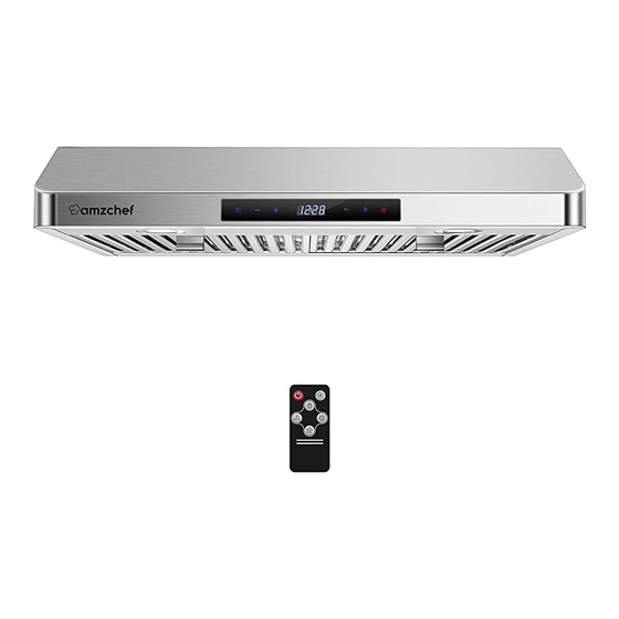
Page 5: Main Parts Name
Main Parts Name Hood Body Baffle filters Opening Size Specifications: Model: 704A/CF2(75) Voltage: 120V/60Hz Air exit: 6" Duct Light: 2x2W LED Motor power: 135W Total power: 139W Filter: Steel baffle filters Control: 3 speed touch control with remote control... -
Page 6: Parts Included
PARTS INCLUDED PARTS LIST A. 5pcs-ST5x40 screws B. 5pcs-Wall anchors C. 4pcs-ST5x16 screws D. 1pc-Remote Control TOOLS NEEDED... -
Page 7: Installation Instructions
INSTALLATION INSTRUCTIONS Warning 1. TO REDUCE THE RISK OF FIRE, USE ONLY METAL DUCT WORK. 2.. GROUNDING INSTRUCTIONS This appliance must be grounded. In the event of an electrical short circuit, grounding reduces the risk of electric shock by providing an escape wire for the electric current. - Page 8 INSTALLATION INSTRUCTIONS Step 1-3 8mm Hole 8mm Hole 1/4" Wall Spacing 1. Drill two 8mm holes in position for Wall Anchor (Part B) placement. 2. Tap Wall Anchors securely into each of the drilled holes. 3. After Wall Anchors have been tapped in place, Insert st5 Screws, but leave 1/4 of the screw sticking out of the wall.
- Page 9 INSTALLATION INSTRUCTIONS Wall Step 6 8" ELECTRICAL ACCESS HOLE 6. Drill a 8" round hole into the bottom of the cabinet. Drill a 1-1/2 hole into the bottom of the cabinet for the Electrical Access hole. 6a. Pull the round duct & power cord through the bottom of the new cabinet holes.
-
Page 10: Installation Procedures
Installation Procedures Safety Warning: Hood may have very sharp edges. Please w ear protective gloves if it is necessary to remove any parts from installing, c leaning or servicing. Installation Height 1. The distance between the stove surface and the underside of the range hood must be in the range of 26"-30"... - Page 12 Parts #supplied Note: The fasteners included may not be suitable to your cabinet. Please check with the installer on proper fasteners to be used based on the material makeup of your cabinet. (A) Range hood (B) Power cord for hard wiring. (C) 6"...
-
Page 14: Operation Instruction
OPERATION INSTRUCTION Function Key and Remote control operation 1. When power on, press 3 seconds to enter into time setting mode. Then press “-” and “+” to set hour, after hour confirmed, press again to set minute, press “-” and “+” to set minute. 2. -
Page 15: Maintenance
Maintenance Caution: Never put your hand into the area housing while the fan is operating. F or the optimal level of operation, c lean the range hood surface, f an, and st ainless steel flter regularly. Use only mild soap or detergent solutions to clean the range hood surface. -
Page 16: To Replace Led Light
To Replace Light Caution: LED light can not replace a new bulb, r eplace the whole LED light. Make sure all the control switches are off, and the r ange hoods unplugged! Please follow below instructions: Take out the fliters and cut off the wire connection of the light, press the spring according to the arrow direction, then y ou can take off the LED light unit.
Need help?
Do you have a question about the 704A/CF2 and is the answer not in the manual?
Questions and answers