
Subscribe to Our Youtube Channel
Related Manuals for Suzuki DF250AP


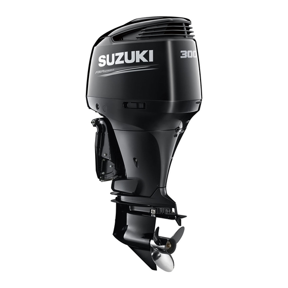
Summary of Contents for Suzuki DF250AP
- Page 1 DF250AP DF300AP OWNER’S MANUAL ENGLISH...
- Page 2 • Do not hold onto the motor cover or any This symbol appears in various locations on other parts of your outboard motor while your Suzuki product to refer you to important getting on or off your boat. information in the owner’s manual.
- Page 3 FOREWORD • Never remove the flywheel cover (except for when emergency starting). Thank you for choosing a Suzuki outboard motor. Please read this manual carefully and NOTE: review it from time to time. It contains important Mounting radio transceiver or navigational...
-
Page 4: Table Of Contents
LOCATION OF SAFETY LABELS ..7 LOCATION OF PARTS......8 MOTOR MOUNTING......9 BATTERY INSTALLATION ....10 USE OF ELECTRICAL ACCESSORIES ........12 SUZUKI KEYLESS START SYSTEM (IF EQUIPPED WITH KEYLESS ........13 START SYSTEM) PROPELLER SELECTION AND INSTALLATION........17 ADJUSTMENT........ -
Page 5: Location
IDENTIFICATION Suzuki recommends that you install a water- separating fuel filter assembly between your NUMBER LOCATION boat’s fuel tank(s) and outboard motor(s). Fuel filtration systems of this type will help prevent The model and identification numbers of your water that may be present in your boat’s fuel outboard motor are stamped on a plate tank(s) from contaminating your motor’s elec-... - Page 6 Always select Unleaded gasoline will extend spark plug life. good quality engine oil. Suzuki recommends the use of SAE 10W-40 or WARNING 10W-30 SUZUKI MARINE 4-CYCLE ENGINE OIL. If SUZUKI MARINE 4-CYCLE ENGINE Gasoline is extremely flammable and toxic. It...
-
Page 7: Location Of Safety Labels
LOCATION OF SAFETY LABELS Read and follow all of the labels on your out- Keep the labels on your outboard motor or fuel board motor or fuel tank. Make sure you under- tank. Do not remove them for any reason. stand all of the labels. -
Page 8: Location Of Parts
LOCATION OF PARTS Motor cover Power trim and tilt (P.T.T.) switch Flush plug Pilot water hole (Reverse side) Engine oil drain plug Clamp bracket Anode Anode Anti-cavitation plate Gear oil level plug Trim tab Gear oil drain plug Water intake hole Water intake hole MULTI-FUNCTION GAUGE KEYLESS FOB... -
Page 9: Motor Mounting
Please contact your authorized Suzuki Marine boat’s “Certification Plate”. Contact your Dealer for details. authorized Suzuki marine dealer if you are unable to locate the hull “Certificate Plate”. NOTE: • The selection of lower unit rotation closely Suzuki strongly recommends that you have relates to the selection of the propeller type. -
Page 10: Battery Installation
When replacement is necessary, they should be replaced as a set. Consult your Suzuki dealer for proper battery installation information. • If your boat application requires additional battery loads, it is recommended that an aux- iliary battery or batteries be installed. - Page 11 Suzuki recommends that you install the termi- • Be sure to attach battery leads correctly. nal cap on the positive battery terminal to pre- •...
-
Page 12: Use Of Electrical Accessories
Be sure to check if the optional 40 A fuse in OPT position is blown, when the second battery for accessories will not be charged. Please ask your authorized Suzuki Marine Dealer for installation of the isolator lead assembly. -
Page 13: Suzuki Keyless Start System (If Equipped With Keyless Start System)
Keyless fob Keyless control unit WARNING NOTE: Please consult with a Suzuki Marine Dealer for the installation of the Keyless Start System. The keyless fob emits radio waves that may interfere with aircraft operations. Also refer to the “Keyless Start System Instruc- tion Manual”... - Page 14 • If the keyless fob is lost, immediately contact may cause ignition, electric shock, or injury. your authorized Suzuki Marine Dealer. Do NOT attempt to disassemble (except for • The keyless fob uses a weak radio wave that...
- Page 15 Switching the communication mode of CAUTION the keyless fob Press and hold the lock button 1 on the key- There is a danger of explosion if the battery is less fob for more than one second to switch replaced with an incorrect type. between ON mode and OFF mode.
- Page 16 To replace the keyless fob battery: 3. Insert a flat blade screwdriver into the slot at 1. Insert a flat blade screwdriver in the slot of mark on the cover to remove the bat- the keyless fob and remove the cover. tery.
-
Page 17: Propeller Selection And Installation
Install a right hand rotation propeller with regular rotation lower unit, or left hand rota- tion propeller with counter rotation lower unit. Please contact your authorized Suzuki Marine Counter rotation lower unit Dealer for more detail. 4. The propeller type suitable for the lower unit... - Page 18 Installing a propeller with either too much or too little pitch will cause incorrect maximum engine speed, which may result in severe damage to the motor. Ask your authorized Suzuki marine dealer to assist you in selecting a suitable propeller for Right hand propeller: your boat.
-
Page 19: Adjustment
• Trim angle too large (Boat tends to “porpoise”) 1. Coat the propeller shaft splines 1 liberally with Suzuki water resistant grease to help prevent corrosion. 2. Place the stopper 2 on the shaft. • Proper trim angle 3. - Page 20 Make a test run in the boat to determine if the WARNING trim angle needs to be adjusted. Adjust the trim angle using the Power Trim and Tilt system. Trim angle greatly affects steering stability. If Refer to the POWER TRIM AND TILT section. the trim angle is too small, the boat may “plow”...
- Page 21 If necessary, The idle speed has been factory adjusted readjust the trim tab. between 600 – 700 r/min in neutral. NOTE: If idle speed cannot be set within the specified range, contact your authorized Suzuki Marine Dealer.
-
Page 22: Meter (Option) Multi-Function Gauge
Motor cover NOTE: There is information that cannot be displayed depending on the model and equipment. NOTE: Consult your authorized Suzuki marine dealer for setting up the multi-function gauge. NOTE: For details the proper handling of the multi- function gauge, refer “OPERATION... - Page 23 BUTTON FUNCTIONS SCREEN SELECTION The multi-function gauge has four buttons: The multi-function gauge can select the display [MENU], [ ], [ ], and [SET]. screen from the following choices. • Engine Speed • Ground Speed/Fuel Information • Fuel Information • All Items Display Screen (Full Item) To select the display screen: Press the [SET] button and select the desired display screen.
- Page 24 No.1 Digital Analog No.2 No.3 No.4 2. Speed/Fuel Information Display Screen 4. All Items Display Screen The speed 1, fuel level 2, sub information This screen displays all the general indica- 3 and time 4 are displayed. tion items for this gauge. The sub information display can be switched This screen can be selected between digital, by pressing the [...
- Page 25 SUB INFORMATION SELECTION 1. Total Operating Hours When the Engine Speed, Ground Speed/Fuel The total operating hours from brand-new Information or Fuel Information screen is dis- engine are displayed. played, press the [ ] or [ ] button to switch the sub Information display in the following sequence.
- Page 26 5. Instantaneous fuel flow 9. Total fuel used This screen indicates the instantaneous fuel This screen indicates the total fuel used of flow of each outboard motor. all outboard motors installed. 6. Total Instantaneous fuel flow 10. Latitude/Longitude This screen indicates the total instantaneous The latitude and longitude of current boat fuel flow of all outboard motors installed.
- Page 27 MENU INFORMATION SELECTION Day or Night The menu screen is displayed when the MENU Press the [ ] or [ ] button to select “Day or button is pressed while any screen is displayed. Night”. Next, select “Day” or “Night” using the While the menu screen is displayed, press the [SET] button.
- Page 28 2. Auto Trim NOTE: • “ A” is not displayed if the trim position does Sets the Auto Trim mode. Set the outboard motor to the full trim down not appear on the multifunction gauge position. Use the [ ] or [ ] buttons to select screen.
- Page 29 Data Output NOTE: Display For details the proper handling of the multi- Tacho function gauge, refer “OPERATION INSTRUCTION MANUAL” packed in the gauge. Speed & Fuel Fuel ON OFF Press the [ ] or [ ] button to select “Data Output”...
- Page 30 6. Keyless You can display the Keyless Start System pass- Device List CAN 2 code. You can also change the passcode. (1) If you have the keyless fob 34200-96L41 • Confirm the keyless fob is within the com- 33920-98L20 munication range of the Keyless Start 33920-98L20 System.
- Page 31 Passcode appears once the [SET] button is pressed after you have entered all 6 digits. Language (2) If you do not have the keyless fob When the keyless start system starts up, English enter your passcode, and you can change it Français within 1 minute after unlocking.
- Page 32 Quantity: set the unit for fuel quantity. Time Press the [SET] button to select the unit. Setting for the time indication. Clock: setting for display/non-display of the clock. Press the [SET] button to select “ON” or “OFF.” G ( US ) G ( IMP ) Quantity Speed Scale HIGH...
- Page 33 The buzzer sound also stops when the cause is eliminated. Position Setting for the gauge and engine position. Consult your authorized Suzuki marine dealer Caution message Caution alarm icon for setting change of “Position”. Component Setting Settings for component.
-
Page 34: Caution System
If the Caution System activates while you are operating your outboard motor, stop the motor as soon as possible and correct the problem or consult your authorized Suzuki marine dealer for assistance. INDICATOR CHECK If equipped with Keyless Start System:... - Page 35 Over-Revolution Caution eliminating the cause. System. If this system activates, stop the engine imme- Consult your authorized Suzuki marine dealer diately, if wind and water conditions make it safe if the Over-Revolution Caution System acti- to do so.
- Page 36 If this system activates for no apparent rea- pilot water hole. If no water is seen, follow the son, there may be a problem with the system. procedures outlined below. Consult your authorized Suzuki marine dealer.
- Page 37 System activated can result in severe In order to cancel this ALERT SYSTEM, quickly engine damage. stop the engine and consult with SUZUKI marine dealer. If the Overheat Caution System activates, stop the engine as soon as possible, wind and water conditions permitting, and inspect the engine according to the above instructions.
- Page 38 However, the caution alarm icon is displayed Suzuki Marine Dealer. until eliminating the cause. This system will be canceled automatically when the battery voltage restores to the proper voltage level.
-
Page 39: Electronic Throttle And Shift Control Caution System
NOTICE Consult your authorized Suzuki marine dealer. If this system activates for no apparent rea- son, there may be a problem with the system. Consult your authorized Suzuki marine dealer. - Page 40 2000 NOTICE r/min. with the remote control lever. If this system activates for no apparent rea- son, there may be a problem with the system. Consult your authorized Suzuki marine dealer. THROTTLE SELECT ONLY NOTE: While the message, “Check Shift Control”, is...
- Page 41 TROLL Mode operation is not available. Consult your authorized Suzuki marine dealer. If this system activates, the “Check Station Set- ting” is displayed on screen. GAUGE COMMUNICATION CAUTION...
-
Page 42: Keyless Start System Caution System (If Equipped With Keyless Start System)
– The correct keyless fob has been authenti- cated by the Keyless Start System. • If this caution system activates continuously, contact your authorized Suzuki Maine Dealer. The “Check Troll System” indication clears when any of the button is pressed in the gauge. - Page 43 • If the message “Keyless Unit Battery Low” is TERY REPLACEMENT section.) displayed, check the following: – The 12 volt battery is in sound condition. – Contact failure of the battery terminal. • If this caution system activates continuously, consult your authorized Suzuki Maine Dealer.
-
Page 44: Diagnostic System
If the diagnostic system activates while you are operating your outboard motor, there is an abnormal condition in one of the sensor sig- nals of the control system. Consult your authorized Suzuki marine dealer for repair of the control system. - Page 45 CANCELLATION 4. If equipped with Keyless Start System: For the single engine: Press and hold the engine switch 1 for more 1. If equipped with Keyless Start System: than two seconds to turn off the power. Press and hold the engine switch 1 for more than two seconds to turn on the power.
- Page 46 Once the system has operated, however, Suzuki strongly recom- mends that the engine oil be replaced before canceling the system activation. • Even if the engine oil has been replaced with the system not operating, it is still necessary to perform the cancellation.
-
Page 47: Engine Stalling Caution System
If this system activates, stop the engine imme- diately, if wind and water conditions are safe to do so, and check the fuel filter/water separator for water. Or consult your authorized Suzuki marine dealer. For inspection and cleaning of the fuel filter,... - Page 48 TILT LIMITER CAM If not equipped with Keyless Start System: If the outboard motor contacts the motor well of the boat while tilting, adjust the tilt limiter cam to WARNING limit maximum tilt position. 1. Place the motor in the normal running posi- The power trim and tilt (PTT) switch on the tion.
- Page 49 MANUAL TILTING If you are unable to tilt the motor using the “Power Trim and Tilt” because of an electrical problem or some other problem, you can move the motor manually. To tilt the motor up or down, turn the manual release valve A two turns counterclockwise, move the motor to the desired position, then retighten the release screw.
-
Page 50: Inspection Before Boating
INSPECTION BEFORE NOTICE BOATING Damage can occur if you use the tilt lock lever other than when the boat is moored or is oth- WARNING erwise stationary. Failure to inspect your boat and motor before The tilt lock lever relieves pressure from the beginning a trip can be hazardous. - Page 51 To fill the engine oil: 1. Remove the oil filler cap. 2. Fill the recommended engine oil to the upper level. 2. Pull out the oil dipstick 4 and wipe oil off with a clean cloth. NOTICE Running the engine with an excessive amount of oil can damage the engine.
-
Page 52: Break-In
BREAK-IN NOTE: You may throttle up beyond the recommended operating range to plane your boat, then imme- Proper operation during this break-in period will diately reduce the throttle to the recommended help ensure maximum life and performance operating range. from your engine. The following guidelines will explain proper break-in procedures. -
Page 53: Operation
CONTROL PANEL (OPTION) OPERATION ENGINE SWITCH (OPTION) Use this switch if equipped with Keyless Start System. • Quickly press the engine switch to start and stop all engines. (The buzzer sounds once.) • Press and hold the engine switch for at least 2 seconds to set the Keyless Start System For dual engine For triple engine... - Page 54 REMOTE CONTROL BOX Start & Stop Switch This is a switch to start and stop the engine. The engine can be started with the remote con- trol handle at the neutral position. SELECT THROTTLE SELECT THROTTLE ONLY ONLY ] (UP) & [ ] (DOWN) Single top mount Flush mount...
- Page 55 20 seconds, and then turn on the power again. seconds, and then turn on the power again. • Consult your authorized Suzuki marine • Consult your authorized Suzuki marine dealer if the station can not be selected.
- Page 56 BEFORE ATTEMPTING TO START THE ENGINE 1. The motor has been lowered into the water. 2. Make sure that the motor fuel hose and the hose from the boat’s fuel tank are securely attached and clamped. WARNING Failure to properly attach the emergency stop switch cord or to take proper precautions to help ensure that the emergency stop switch 3.
- Page 57 STARTING THE ENGINE (3) To start each engine individually, press and hold the engine switch for at least 2 seconds WARNING to set Keyless Start System to ON state (buzzer sounds once). Then press the con- trol panel start/stop switch to start each Exhaust gas contains carbon monoxide, a engine individually.
- Page 58 If you notice that water does not spray out of the pilot water hole, stop the engine as soon as possible and consult your Suzuki Marine Dealer. NOTE: If equipped with Keyless Start System: The communication range is a distance of 1 m (40 in) between the keyless fob and the keyless control unit.
- Page 59 If equipped with Keyless Start System: 3. Enter a 6-digit passcode. Use the [ ] or [ ] buttons to select a num- EMERGENCY START ber for each digit. If the keyless fob cannot be used due to a dead Press the [SET] button to move to the next keyless fob battery or other issue, you can start digit.
- Page 60 SHIFTING AND SPEED CONTROL To start the engine: 5. Make sure the motor is in “NEUTRAL”. NOTICE • Severe engine damage may occur if (a) engine speed is not allowed to return to idle and boat speed is not reduced when shift- ing from “FORWARD”...
- Page 61 A detent or notch is present on all Suzuki con- NOTE: trol boxes to provide a “feel” for positions A, B, • When the engine stops, the clutch moves to and neutral. Always shift quickly and firmly from the neutral position irrespective of the posi- neutral to position A or B to prevent abnormal tion of the remote control lever.
- Page 62 STOPPING THE ENGINE 4. Turn the Keyless Start System to OFF (locked) status by one of the following meth- NOTE: ods. When it is necessary to stop the engine in an • Make sure that the keyless fob is within emergency, pull the emergency stop switch lock the communication range of the keyless plate by pulling the emergency stop switch...
- Page 63 If not equipped with Keyless Start System: NOTICE To stop the engine: 1. Shift into “NEUTRAL”. If the Keyless Start System is in ON state 2. After operating at full throttle, cool off the while the engine is not running, the battery engine a few minutes by allowing it to idle or will be discharged.
- Page 64 MOORING NOTICE The motor should be tilted up out of the water when you moor the boat in shallow water or if If the main switch is left ON when the engine the motor will not be used for some time, to pro- is not running, the battery will discharge.
- Page 65 650 r/min to 1200 r/min using the ] or [ ] button. NOTE: Please contact your authorized Suzuki Marine Dealer for more information. Setting the Troll Mode 1. Shift into forward or reverse gear and make sure that the throttle is fully closed (in-gear idle speed).
- Page 66 Example of the troll mode display on the Multi- NOTE: Function Gauge that can operate the troll • This system will not function properly until mode. engine is at normal operating temperature. • If the [MENU] button is pressed and held while the remote control lever is in neutral, the mode will not switch to TROLL Mode.
- Page 67 – trol handles are shifted into forward or NOTE: reverse at the fully closed throttle position Please contact your authorized Suzuki Marine (in-gear idle speed) before pressing the Dealer for more information. troll mode switch. In-gear idle speed of all engines is con- –...
-
Page 68: Motor Removal And Transporting
50 r/min. your authorized Suzuki Marine Dealer to do the work for you. NOTE: Shift operation and throttle control remain oper- ational, even in troll mode. MOTOR TRANSPORTING... - Page 69 (2) Loosen the vapor separator drain screw 2 (3) After draining, retighten the vapor separator drain screw 2. and drain the gasoline into a suitable con- tainer. 3. Rest the motor on a case protector with the port side downwards as shown. WARNING Spilled fuel or fuel vapor can cause a fire and is hazardous to health.
-
Page 70: Trailering
TRAILERING NOTICE When trailering your boat with the motor If you let the lower unit of your outboard sit attached, keep the motor in the normal operat- higher than the power head during transport- ing position unless there is not enough ground ing or storing, water may trickle into the clearance. -
Page 71: Inspection And Maintenance
INSPECTION AND MAINTENANCE MAINTENANCE SCHEDULE WARNING It is important to inspect and maintain your out- board motor regularly. Follow the chart below. Exhaust gas contains carbon monoxide, a At each interval, be sure to perform the indi- dangerous gas that is difficult to detect cated service. - Page 72 When replacing Be sure to have maintenance performed parts on your outboard motor, Suzuki strongly according to the schedule in the above chart. recommends that you use genuine Suzuki Suzuki recommends that only your authorized parts or their equivalent.
- Page 73 A normally operating spark plug is very light- brown in color. If the standard plug is not suit- able for your operating, consult your authorized Suzuki Marine Dealer. 2. Remove the air duct guard 2. 3. Remove the bolt securing the ignition coil.
- Page 74 To maintain a strong spark, you should clean NOTICE and adjust the plugs at the intervals shown in the maintenance chart. Remove carbon depos- Use of improper spark plugs or improperly its from the spark plugs using a small wire tightening spark plugs can cause severe brush or spark plug cleaner, and adjust the gap engine damage.
- Page 75 Consult your authorized Never perform any ENGINE OIL procedure Suzuki Marine Dealer if it is necessary to with the motor running, as serious injury can replace them.
- Page 76 7. Check the engine oil level. CAUTION The engine oil temperature may be high enough to burn your fingers when the drain plug is loosened. Wait until the drain plug is cool enough to UPPER LIMIT touch with bare hands before removing it. 4.
- Page 77 If the gear oil has a milky color, it is contami- nated with water. Immediately contact your 3. After the oil has drained completely, inject authorized Suzuki marine dealer for advice. the specified gear oil into the gear oil drain Do not operate your outboard until the oil is...
- Page 78 3. Remove the bolts 1 securing the fuel filter The low pressure fuel filter must be replaced by cap 2 in place. an authorized Suzuki Marine Dealer periodi- cally. Replace low pressure fuel filter at every 400 hours (2 years).
- Page 79 If any water exists in the fuel filter cup, remove the cup and drain the water. Always dispose of excess fuel safely. For questions, consult your authorized Suzuki Marine Dealer. LUBRICATION Proper lubrication is important for the safe, smooth operation and long life of each working part of your outboard motor.
- Page 80 NOTE: If it is difficult to inject the grease in correct vol- Clutch lever ume, consult your Authorized Suzuki Marine Dealer. ANODES AND BONDING WIRES Anodes The motor is protected from exterior corrosion by anodes.
- Page 81 • Periodically clean anodes with a wire brush to remove any coating which might decrease their protective ability. NOTE: Consult your authorized Suzuki Marine Dealer for inspection and replacement of internal anodes attached to the cylinder block/cylinder head.
- Page 82 BATTERY Bonding wires The battery solution level must be kept between Bonding wires are used to electrically connect the MAX and the MIN level lines at all times. If the engine components so they exist in a com- the level drops below the MIN level line, add mon ground circuit.
-
Page 83: Flushing The Water Passages
Flush the water passages as follows. ENGINE RUNNING – Vertical position – Suzuki recommends that you flush the water passages by using this method. To flush the water passages, you must obtain a commercially available engine flush device. - Page 84 5. Place the remote control lever in the “NEU- NOTICE TRAL” position with the propeller removed, start the motor and allow it to run at idle. Severe engine damage can occur in as little as 6. Readjust the water flow, if necessary, so 15 seconds if the engine is started without that there is still plenty of excess water flow- supplying water to the cooling system.
-
Page 85: Submerged Motor
SUBMERGED MOTOR 3. Install garden hose by using a hose connec- tor matched to flushing port thread B. Thread B: 0.75 – 11.5 NHR (American stan- A motor that has been accidentally submerged dard hose coupling threads for garden hose in water must be overhauled as soon as possi- applications.) ble to prevent corrosion. -
Page 86: Storage Procedure
STORAGE PROCEDURE 7. Take the motor to your authorized Suzuki Marine Dealer as soon as possible to be overhauled. MOTOR STORAGE When storing your motor for a long period of NOTICE time (for example, at the end of the boating sea- son), it is recommended that you take your motor to your authorized Suzuki Marine Dealer. -
Page 87: After Storage
AFTER STORAGE NOTICE When taking your motor out of storage, follow Severe engine damage can occur in as little as the procedure below to return it to operating 15 seconds if the engine is started without condition: supplying water to the cooling system. 1. -
Page 88: Troubleshooting
Caution system is activated (Caution If you are not sure about the proper action to buzzer sounds. Caution LEDs lights.): correct a problem, consult your Suzuki marine • Cooling water passage is clogged. dealer. • Thermostat is failed. - Page 89 FUSE Engine vibrates excessively: 1. If equipped with Keyless Start System: • Propeller is damaged. Turn the Keyless Start System OFF. • Engine mounting bolts or clamp screws are loose. If not equipped with Keyless Start System: Turn the ignition key to the “off” position. The Keyless Start System does not turn 2.
- Page 90 If a new fuse blows in a short time after instal- lation, you may have a major electrical system problem. Consult your SUZUKI marine dealer. Sub battery cable fuse case 5. Inspect the fuse and replace with new fuse if needed.
-
Page 91: Specifications
SPECIFICATIONS Item DF250AP DF300AP Engine Type 4 Stroke Number of Cylinders Bore and Stroke 98.0 × 89.0 mm (3.86 × 3.50 in) Piston Displacement 4028 cm (245.7 cu. in) Maximum output 183.9 kW (250PS) 220.7 kW (300PS) Full Throttle Operating Range 5500 –... -
Page 92: Reminder System
FLOWCHART OF OIL CHANGE REMINDER SYSTEM Action Starting operation (*1) (*4) Indication Cancellation (*2) (*4) Indication Cancellation (*3) (*4) Indication Cancellation (*3) (*4) Indication Cancellation *1 : Lapse of initial 20 hour’s operation *2 : Lapse of 80 hour’s operation *3 : Lapse of 100 hour’s operation Repeat *4 : When performing cancellation before system activation...
Need help?
Do you have a question about the DF250AP and is the answer not in the manual?
Questions and answers