Table of Contents
Advertisement
Quick Links
Advertisement
Table of Contents

Related Manuals for BeagleBoard X15


Summary of Contents for BeagleBoard X15
- Page 1 BEAGLEBOARD-X15 REV C Quick Start Guide Rev 0.1 July 2017...
-
Page 2: Table Of Contents
SERIAL DEBUG ..............................13 TERMINAL SETUP ..............................13 PLUG in POWER ..............................13 POWER LEDS ................................ 14 Turn on Hd monitor ............................. 14 TURN ON X15 POWER............................15 BOOTING ................................15 USER LEDS ................................15 TESTING ................................... 17 DEBUG: ................................17 ETHERNET ................................ - Page 3 Figure 5 – TOP Side of X15 Major Interfaces ......................... 5 Figure 6 – X15 Side View Bottom Edge .......................... 5 Figure 7 - Locations of major ICs on the X15 ......................... 6 Figure 8 - Desktop Configuration ..........................10 Figure 9 - ETHERNET PORTS ............................
-
Page 4: What's The In The Box
WHAT’S THE IN THE BOX In the box you will find a BEAGLEBOARD-X15 board inside an ESD bag. Figure 1 – BEAGLEBOARD-X15 Box Contents BEAGLEBOARD-X15 QUICK START GUIDE... -
Page 5: Top Edge And Bottom Side
ENET 0 ENET 1 ENET X2 ESATA HDMI DC JACK PWR ON Figure 1 – BEAGLEBOARD-X15 Side View of Top Edge RTC XTAL 5A FUSE 20pin JTAG µSD CAGE USB CLIENT Figure 2 – Bottom side of BEAGLEBOARD-X15 BEAGLEBOARD-X15 QUICK START GUIDE... -
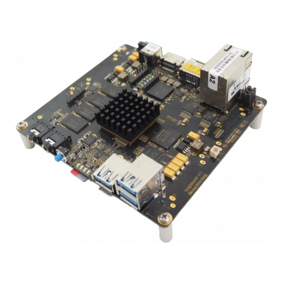
Page 6: Top Side And Bottom Edge
GET VERY HOT AUDIO OUT USER LEDs USB3 USB3 x2 AUDIO IN RESET Figure 3 – TOP Side of BEAGLEBOARD-X15 Major Interfaces RESET USB Port 0 USB Port 2 USB Port 1 µSD USB CLIENT Figure 4 – BEAGLEBOARD-X15 Side View Bottom Edge... -
Page 7: Major Components
MAJOR COMPONENTS Figure 5 shows the major IC and components on the BEAGLEBOARD-X15. PMIC AM5728 nFBGA SERDES CLK GEN 10/100/1000 U14 U15 ENET PHY x2 DDR3 4Gb x4 eMMC 4Gx8 Regulator AUDIO CODEC Figure 5 - Locations of major ICs on the BEAGLEBOARD-X15... -
Page 8: Check It Out
WHAT YOU WILL NEED Table 1 shows the accessories needed to test all BEAGLEBOARD-X15 peripherals. Some of these items may need to be purchased if the user does not already own them. For power supply and serial cables please observe power requirements when purchasing. - Page 9 4GB to 16GB Class 10 Standard Adapter eSATA ADAPTER CABLE eSATA to SATA cable Combo cable SATA DRIVE SATA HDD - Hard Disk Drive SATA SSD - Solid State Drive BEAGLEBOARD-X15 QUICK START GUIDE...
- Page 10 Or to boot from USB3 WIRELESS KEYBOARD/MOUSE Wireless combo will save USB ports used Less wire clutter Besides the accessories mentioned it is assumed the user has a PC or Laptop running Linux or Windows. BEAGLEBOARD-X15 QUICK START GUIDE...
-
Page 11: Setup Instructions
Figure 8. It allows you to create your code to make the board do whatever you need it to do. It will however require certain common PC accessories. These accessories and instructions are described in the following section Figure 6 - Desktop Configuration Additionally an Ethernet cable can be connected for network access. BEAGLEBOARD-X15 QUICK START GUIDE... -
Page 12: Plug In Your Cables
PLUG IN YOUR CABLES ETHERNET There are two ports on the Ethernet connector on BEAGLEBOARD-X15. Plug cable into either port. Notice the orientation of cable insertion between the two ports in Figure Figure 7 - ETHERNET PORTS HDMI Plug in HMDI cable into P11 HDMI connector on the top edge of the BEAGLEBOARD-X15 board. -
Page 13: Keyboard And Mouse
USB port including P6 eSATA connector. Figure 9 – Keyboard Transmitter AUDIO To playback and record audio, insert speaker cable into Audio OUT jack of the BEAGLEBOARD-X15 and an audio source into the Audio IN jack. Figure 10 – AUDIO JACKS MICRO SD CARD On the bottom edge of the BEAGLEBOARD-X15 board, on the bottom side is the micro SD card cage. -
Page 14: Serial Debug
P1 jack. This is a 2.5mm center contact and requires a supply that comes with a 2.5mm jack or an adapter to 2.5mm. See Table 1 for more info. Figure 17 – DC IN JACK P1 BEAGLEBOARD-X15 QUICK START GUIDE... -
Page 15: Power Leds
D41 - 12V Present LED Figure 19 – DC 12V LED TURN ON HD MONITOR Once power is connected, turn on HDMI monitor. Change input to the HDMI port the BEAGLEBOARD-X15 is connected Figure 14 – MONITOR POWER BUTTON BEAGLEBOARD-X15 QUICK START GUIDE... -
Page 16: Turn On X15 Power
LED D41 will glow. D41 - 12V Present LED To turn ON the BEAGLEBOARD-X15 main power press the blue momentary switch S1. This will cause LED D3 to glow showing that the board power is ON. - Page 17 Once the BEAGLEBOARD-X15 interfaces are connected your system is ready to test. The next section will go through what you can test. Figure 18 - Complete BEAGLEBOARD-X15 system ready for test BEAGLEBOARD-X15 QUICK START GUIDE...
-
Page 18: Testing
Figure 19 - Terminal activity on the Tera Term A few seconds after the board power is turned on, the image in eMMC will boot and the Debian desktop will soon show up on the HDMI monitor. BEAGLEBOARD-X15 QUICK START GUIDE... -
Page 19: Ethernet
ETHERNET Assuming the Ethernet cable is connected to one of the ENET ports on the BEAGLEBOARD-X15 a quick test can be performed by pointing the mouse to the bottom left corner of the Desktop and clicking the Debian menu logo. -
Page 20: Speakers
SPEAKERS To test the sound of your BEAGLEBOARD-X15 you can open a sound file or via file and play it back. In the example below, a simple file is played via the Chromium Web browser. Inserting a USB drive into the USB3.0 ports is one option. - Page 21 Click ‘Open in file Manager’ to see the contents of the flash drive. Proceed to open the sound file. In case there is no music player installed yet, open the wav file with Chromium Brower. Then click play. Figure 24 - Open and Play sound file BEAGLEBOARD-X15 QUICK START GUIDE...
-
Page 22: Esata
To adjust volume make sure your speakers are connected and the speaker volume is turned to a nominal volume. The BEAGLEBOARD-X15 volume can be adjusted by clicking on the lower right hand side left of the clock (icon missing in this example) and adjusting the volume lever up and down. -
Page 23: Power On And Reset
When plugged in the eSATA or USB will be listed on the Debian Desktop as shown below: Figure 27 - Attached drives show up in Debian pop-up window POWER ON AND RESET To power OFF the board you can Press-and-Hold the power button for 12 seconds. BEAGLEBOARD-X15 QUICK START GUIDE... -
Page 24: Fan
Figure 28 - Powering OFF using the shutdown command To RESET the board you can press the RESET button S2. Pressing once should reboot the board. Figure 29 - The RESET Button P2 BEAGLEBOARD-X15 QUICK START GUIDE... - Page 25 The BEAGLEBOARD- X15 is comes does not come with a heatsink or fan installed but they can be added if required. The heatsink can be applied to the processor prior to sticking it onto the processor. The fan will connect to the socket located on the top side of the board, on the left edge as shown in Figure 36 .
- Page 26 Table 2 shows the parts list for the BEAGLEBOARD-X15 Heatsink and Fan Assembly. Table 2 – Heatsink and Fan Bill of Materials COPAL F251R-05LB FAN AXIAL 25X10MM 5VDC WIRE Machine Screw McMaster 96640A059 Box of 100 4-40 Flat head Machine screws 5/8”...
Need help?
Do you have a question about the X15 and is the answer not in the manual?
Questions and answers