Advertisement
Quick Links
Advertisement

Related Manuals for BeagleBoard BeagleBone AI-64


Summary of Contents for BeagleBoard BeagleBone AI-64
- Page 1 BeagleBone AI-64 System Reference Manual...
- Page 2 BeagleBone AI-64 System Reference Manual...
- Page 3 • Jason Kridner • Robert P J Day • Gerald Coley Supply comments and errors via: https://git.beagleboard.org/beagleboard/beaglebone-ai-64/-/ issues All information in this document is subject to change without notice. For an up to date version of this document refer to: https://git.beagleboard.org/beagleboard/...
- Page 4 This LICENSE does not apply to BeagleBoard.org Foundation trademarks. BEAGLEBONE AI-64 ADDITIONAL TERMS BeagleBoard.org Foundation and logo-licensed manufacturers provide the board under the following conditions: The user assumes all responsibility and liability for proper and safe handling of the goods. Further, the user indemnifies the Supplier from all claims arising from the handling or use of the goods.
- Page 5 products, and therefore our arrangement with the user is not exclusive. The Supplier assumes no liability for applications assistance, customer product design, software performance, or infringement of patents or services described herein. UNITED STATES FCC AND CANADA IC REGULATORY COMPLIANCE INFORMATION The board is annotated to comply with Part 15 of the FCC Rules.
- Page 6 FDA Class III or similar classification, then you must specifically notify Suppliers of such intent and enter into a separate Assurance and Indemnity Agreement. Mailing Address: BeagleBoard.org Foundation 4467 Ascot Ct Oakland Twp, MI 48306 U.S.A. WARRANTY: The board assembly as purchased is warranted against defects in materials and workmanship for a period of 90 days from purchase.
- Page 7 All boards received without RMA approval will not be worked on.
- Page 8 BeagleBoard.org Foundation. BeagleBoard.org Foundation A Michigan,USA based 501(c)(3) non-profit corporation. BeagleBone A family of BeagleBoard.org boards from the original mint-tin sized computer and registered trademark of the BeagleBoard.org Foundation. Board In this document, it refers to BeagleBone AI-64.
-
Page 9: Chapter 1. Introduction
The board will primarily be referred to in the remainder of this document simply as the board, although it may also be referred to as AI-64 or BeagleBone AI-64 as a reminder. This design is subject to change without notice as we will work to keep improving the design as the product matures based on feedback and experience. -
Page 10: Chapter 2. Change History
Khatri Jason Kridner 2.2. Board Changes Be sure to check the board revision history in the schematic file in the BeagleBone AI-64 git repository. Also check the issues list. 2.2.1. Rev B We are starting with revision B based on this being an update to the original BeagleBone AI. -
Page 11: Chapter 3. Connecting Up Your Beaglebone
All the BeagleBone AI-64 conections ports we will use in this chapter are shown in the figure below. Figure 1. BeagleBone AI-64 conections ports. 3.1. Methods of operation 1. Tethered to a PC, or 2. As a standalone development platform in a desktop PC configuration with a Display Port Monitor, power supply, keyboard, and mouse 3.2. - Page 12 Get yourself a USB-A to USB-C and you have a setup for the tethered scenario and creates an out of box experience where the board can be used immediately with no other equipment needed. Figure 2. BeagleBone AI-64 box content 3.3. Main Connection Scenarios This section will describe how to connect the board for use.
- Page 13 3.4. Tethered To A PC In this configuration, the board is powered by the PC via the provided USB cable—no other cables are required. The board is accessed either as a USB storage drive or via the browser on the PC. You need to use either Firefox or Chrome on the PC, Internet Explorer will not work properly.
- Page 14 Figure 4. USB Connection to the Board 2. Connect the USB-A end of thecable tp your PC or laptop USB port as shown in the Connection to the PC/Laptop figure below. Figure 5. USB Connection to the PC/Laptop 3. The board will power on and the power LED will be on as shown in Board Power LED figure below.
- Page 15 Figure 6. Board Power LED 4. When the board starts to the booting process started by the process of applying power, the LEDs will come on in sequence as shown in Board Boot Status figure below. It will take a few seconds for the status LEDs to come on, so be patient.
- Page 16 enumerated. Once the board appears as a storage drive, do the following: 1. Open the USB Drive folder. 2. Click on the file named start.htm 3. The file will be opened by your browser on the PC and you should get a display showing the Quick Start Guide.
- Page 17 M.2 WiFi module can provide wireless networking. 3.5.2. Connecting Up the Board 1. Connect the miniDP to DP or active miniDP to HDMI cable from your BeagleBone AI-64 to your monitor. Figure 9. Connect miniDP-DP or active miniDP-HDMI cable to BeagleBone AI-64 2.
- Page 18 Figure 10. Display adaptors 3. If you have wired/wireless USB keyboard and mouse such as seen in Keyboard and Mouse figure below, you need to plug the receiver in the USB host port of the board as shown in Keyboard and Mouse figure.
- Page 19 Figure 12. Ethernet Cable Connection 5. The final step is to plug in the DC power supply to the DC power jack as shown in External DC Power figure below. Figure 13. External DC Power 6. The cable needed to connect to your display is a miniDP-DP or active miniDP-HDMI. Connect the miniDP connector end to the board at this time.
- Page 20 The LEDs will be flashing in an erratic manner as it boots the Linux kernel. Figure 15. BeagleBone AI-64 LEDs While the four user LEDS can be over written and used as desired, they do have specific...
- Page 21 meanings in the image that is shipped with the board once the Linux kernel has booted. ◦ USR0 is the heartbeat indicator from the Linux kernel. ◦ USR1 turns on when the microSD card is being accessed ◦ USR2 is an activity indicator. It turns on when the kernel is not in the idle loop. ◦...
-
Page 22: Chapter 4. Beaglebone Ai-64 Overview
Chapter 4. BeagleBone AI-64 Overview BeagleBone AI-64 is the latest addition to BeagleBoard.org family and like its predecessors, is designed to address the open-source Community, early adopters, and anyone interested in a low cost 64-bit Dual Arm® Cortex®-A72 processor based Single Board Computer (SBC). - Page 23 Bluetoot TODO: add cape compatibility details 4.2. BeagleBone AI-64 Features and Specification This section covers the specifications and features of the board and provides a high level description of the major components and interfaces that make up the board.
- Page 24 This section describes the key components on the board. It provides information on their location and function. Familiarize yourself with the various components on the board. 4.3.1. Board components BeagleBone AI-64 board components figure below shows the locations of the connectors, LEDs, and switches on the PCB layout of the board.
- Page 25 Figure 17. BeagleBone AI-64 board components • DC Power is the main DC input that accepts 5V power. • Power Button alerts the processor to initiate the power down sequence and is used to power down the board. • GigaBit Ethernet is the connection to the LAN.
- Page 26 • TI TDA4VM processor. • 4GB LPDDR4 Dual Data Rate RAM memory. • Ethernet PHY physical interface to the network. • eMMC onboard MMC chip that holds up to 16GB of data.
-
Page 27: Chapter 5. Beaglebone Ai-64 High Level Specification
Chapter 5. BeagleBone AI-64 High Level Specification BeagleBone AI-64 Key Components figure below shows the high level block diagram of BeagleBone AI-64 board surrounding TDA4VM SoC. BeagleBone AI -64 Power Input 1 Power Input 2 DC Jack USB TYPE C MCU_BOOTMODE03 &... - Page 28 Multicore SoC architecture platform and it is targeted for the reliability and low-latency needs of the automotive market provide for a great general purpose platform suitable for industrial automation, mobile robotics, building automation and numerous hobby projects. The SoC designed as a low power, high performance and highly integrated device architecture, adding significant enhancement on processing power, graphics capability, video and imaging processing, virtualization and coherent memory support.
- Page 29 SoC, among others: • One dual-core 64-bit Arm Cortex-A72 microprocessor subsystem at up to 2.0 GHz and up to 24K DMIPS (Dhrystone Million Instructions per Second) • Up to three Microcontroller Units (MCU), based on dual-core Arm Cortex-R5F processor running at up to 1.0 GHz, up to 12K DMIPS •...
- Page 30 • Flash memory interfaces, including: ◦ One Octal SPI (OSPI) interface and one Quad SPI (QSPI) or one QSPI and one HyperBus ◦ One General Purpose Memory Controller (GPMC) with Error Location Module (ELM) and 8- or 16- bit-wide data bus width (supports parallel NOR or NAND FLASH devices) ◦...
- Page 31 • DDR Subsystem (DDRSS) with Error Correcting Code (ECC), supporting LPDDR4 • 1KB RAM with ECC support for C71x boot vectors • 2KB RAM with ECC support for A72 and R5F boot vectors • 512KB On-Chip SRAM protected by ECC •...
- Page 32 WKUP Domain MAIN Domain H 264/5 Decoder WKUP_C TRL_MMR D5520MP2 A72S S 2 R5FS S × C 66S S WKUP_PS C H 264 Encoder DMS C VXE384MP2 WKUP_PLLC TRL 2 Arm × 1× C 71x 4 Arm × 2 C 66x ×...
- Page 33 TODO: This section needs more work and references to greater detail. Other boot modes are possible. Software to support USB and serial boot modes is not provided by beagleboard.org. Please contact TI for support of this feature. A switch is provided to allow switching between the modes.
- Page 34 5.3. Power Management The TPS65941213 and TPS65941111 power management device is used along with a separate LDO to provide power to the system. TheTPS65941213 and TPS65941111 version provides for the proper voltages required for the LPDDR4. This is the same device as used on the original BeagleBone with the exception of the power rail configuration settings which will be changed in the internal EEPROM to the TPS65941213 and TPS65941111 to support the new voltages.
- Page 35 5.8. Reset Button When pressed and released, causes a reset of the board. 5.9. Power Button This button takes advantage of the input to the PMIC for power down features. 5.10. Indicators There are a total of six green LEDs on the board. •...
-
Page 36: Chapter 6. Beaglebone Ai-64 Mechanical
Chapter 6. BeagleBone AI-64 Mechanical 6.1. Dimensions and Weight Size: 102.5 x 80 (4" x 3.15") Max height: TODO PCB Layers: TODO PCB thickness: 2mm (0.08") RoHS Compliant: Yes Weight: 192gm 6.2. Silkscreen and Component Locations Figure 20. Board Dimensions... - Page 37 Figure 21. Top silkscreen...
- Page 38 Figure 22. Bottom silkscreen...
-
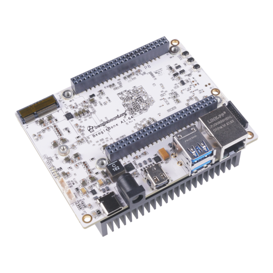
Page 39: Chapter 7. Pictures
Chapter 7. Pictures Figure 23. BeagleBone AI-64 front Figure 24. BeagleBone AI-64 back... - Page 40 Figure 25. BeagleBone AI-64 back with heatsink Figure 26. BeagleBone AI-64 front at 45° angle...
- Page 41 Figure 27. BeagleBone AI-64 back at 45° angle Figure 28. BeagleBone AI-64 back with heatsink at 45° angle...
- Page 42 Figure 29. BeagleBone AI-64 ports...
-
Page 43: Chapter 8. Support Information
8.1. Hardware Design You can find all BeagleBone AI-64 hardware files here. 8.2. Software Updates You can download and flash the supported image onto your BeagleBone AI-64 from this source. To see what SW revision is loaded into the eMMC check /etc/dogtag. It should look something like... - Page 44 Bibliography Datasheets ▪ TDA4VM Jacinto™ Processors for ADAS and Autonomous Vehicles Silicon Revisions 1.0 and 1.1 datasheet (Rev. J) ▪ DRA829/TDA4VM Technical Reference Manual (Rev. C) Books ▪ BeagleBone Cookbook ▪ Bad to the Bone ▪ Exploring BeagleBone...
- Page 45 Index...
Need help?
Do you have a question about the BeagleBone AI-64 and is the answer not in the manual?
Questions and answers