Advertisement
INSTALLATION AND MAINTENANCE INSTRUCTIONS
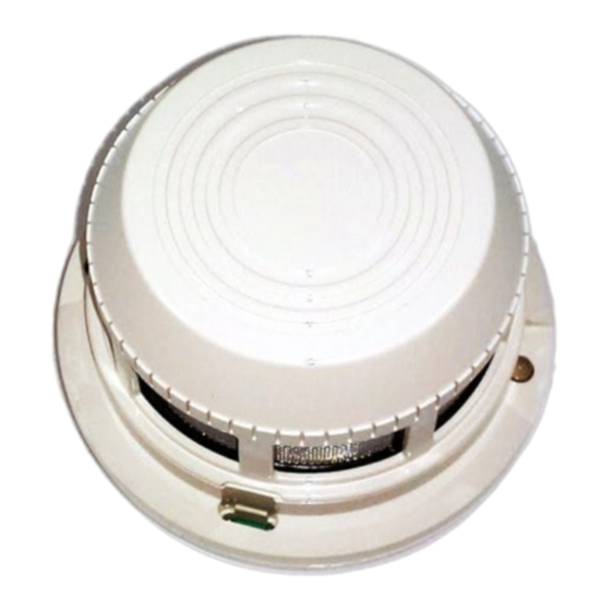
FOR MODEL SDX-551/SDX-551TH PLUG-IN INTELLIGENT
PHOTOELECTRONIC SENSOR WITH COMMUNICATIONS
Before installing sensors, please thoroughly read the system wiring and installation manual, which provides detailed in-
formation on sensor spacing, placement, zoning, and special applications. Copies of these manuals are available from
Notifier.
GENERAL DESCRIPTION
The model SDX-551/SDX-551TH photoelectronic sensor utilizes a state-of-the-art, optical sensing chamber. This sensor
is designed to provide open area protection, and to be used with compatible UL-listed NOTIFIER control panels only.
Suitable for use with panel Model AM2020, Loop Interface Board, LIB-200; compatibility ID:A; maximum number of sen-
sors per loop is 99. See 155-531, Revision A, for installation and wiring diagrams.
Two LEDs on each sensor light to provide a local 360° visibility of the sensor indication. The LEDs can be latched ON by
code command from the panel for an alarm indication. The LEDs can also be unlatched to the normal condition by code
command. Remote LED annunciator capability is available as an optional accessory (part no. RA400Z).
The SDX-551TH adds a thermal heat collector that alarms at a fixed temperature of 135° F.
SPECIFICATIONS
Diameter:
Height:
Weight:
Installation Temperature Range
SDX-551:
SDX-551TH:
Operating Humidity Range:
Mounting:
Maximum Air Velocity:
Voltage Range:
Standby Current:
LED Current:
WIRING GUIDE
Refer to the installation instructions for the particular plug-in base being used: 1) for the BX-501 base (D550-01-01); 2) for
the B501 base (D550-02-00); 3) for the RMK400 used with the B501 base (D450-07-00). Bases are provided with screw
terminals for power, ground, and remote annunciator connections. See Figure 1.
NOTE: All wiring must conform to applicable local codes, ordinances, and regulations.
NOTE: Verify that all sensor bases are installed and that the wiring polarity is correct at each base.
D500-02-00
www.PDF-Zoo.com
Division of Pittway Corporation
6.1 inches (15.5 cm) installed in BX-501
4.1 inches (10.4 cm) installed in B501
2.3 inches (5.8 cm)
Add 0.5 inches (1.3 cm) for thermal models
9.6 ounces (272 gm)
32° to 120° F (0° to 49° C)
32° to 100° F (0° to 38° C)
10% to 93% Relative Humidity
BX-501 flanged base
B501 flangeless base
B501 with RMK400 recessed mounting kit
3000 Ft./Min. (15 m/S)
15 to 32 Volts DC Peak
150 µA @ 24 VDC
6 mA @ 24 VDC
1
Notifier, 12 Clintonville Rd., Northford, CT, 06472 (203) 484-7161
firealarmresources.com
®
I56-309-03
Advertisement
Table of Contents

Related Manuals for Pittway Notifier SDX-551


Summary of Contents for Pittway Notifier SDX-551
- Page 1 ® Division of Pittway Corporation INSTALLATION AND MAINTENANCE INSTRUCTIONS FOR MODEL SDX-551/SDX-551TH PLUG-IN INTELLIGENT PHOTOELECTRONIC SENSOR WITH COMMUNICATIONS Before installing sensors, please thoroughly read the system wiring and installation manual, which provides detailed in- formation on sensor spacing, placement, zoning, and special applications. Copies of these manuals are available from Notifier.
- Page 2 WARNING: Remove power from the loop before installing sensors. 1. Install sensors: a. Verify that the sensor type matches the type written on the label on the base. b. Set the sensor to a desired address and then write the address on the label on the base. c.
- Page 3 NOTE: If the sensor’s sensitivity limits or the MOD400R limits do not appear on the back of the sensor, the MOD400R is not suitable for field sensitivity testing of that unit. TEST MODULE TEST PAINTED MAGNET SURFACE SOCKET TEST MAGNET A78-1977-00 Figure 2.
- Page 4 2. Vacuum the screen carefully without removing it. If further cleaning is required continue with Step 3, otherwise skip to Step 6. 3. Remove the screen by pulling it straight out. Vacuum the inside. 4. Clean the vaned chamber piece by vacuuming or blowing out dust and particles. 5.
Need help?
Do you have a question about the Notifier SDX-551 and is the answer not in the manual?
Questions and answers