
Related Manuals for Honda EU32i


Summary of Contents for Honda EU32i
- Page 1 GENERATOR EU32i OWNER'S MANUAL MANUEL DE L'UTILISATEUR BEDIENUNGSANLEITUNG MANUALE DELL'UTENTE...
- Page 2 Honda EU32i OWNER’S MANUAL Original instructions MANUEL DE L’UTILISATEUR Notice originale BEDIENUNGSANLEITUNG Originalbetriebsanleitung MANUALE DELL'UTENTE Traduzione delle istruzioni originali...
- Page 4 The information and specifications included in this publication were in effect at the time of approval for printing. Honda Motor Co., Ltd. reserves the right, however, to discontinue or change specifications or design at any time without notice and without incurring any obligation whatsoever.
-
Page 5: Introduction
When your generator needs scheduled maintenance, keep in mind that your Honda servicing dealer is specially trained in servicing Honda generators. Your Honda servicing dealer is dedicated to your satisfaction and will be pleased to answer your questions and concerns. - Page 6 INTRODUCTION A FEW WORDS ABOUT SAFETY Your safety and the safety of others are very important. We have provided important safety messages in this manual and on the generator. This information alerts you to potential hazards that could hurt you or others.
-
Page 7: Table Of Contents
CONTENTS INTRODUCTION ....................2 GENERATOR SAFETY ..................7 IMPORTANT SAFETY INFORMATION................7 Operator Responsibility....................7 Carbon Monoxide Hazards..................... 8 Electric Shock Hazards ..................... 9 Fire and Burn Hazards ....................10 Refuel With Care.......................10 Explosion proof ........................11 Vehicles and Transportation Hazards...............11 Disposal ..........................11 Disposing of generator....................11 SAFETY LABEL LOCATIONS....................12 INITIAL USE INSTRUCTIONS ................ - Page 8 CONTENTS BEFORE OPERATION..................34 ARE YOU READY TO GET STARTED? ................34 Knowledge .........................34 IS YOUR GENERATOR READY TO GO?................34 Check the Engine ......................35 AC Appliance and Power Cord..................35 ENGINE OIL LEVEL CHECK ....................37 AIR FILTER CHECK .........................38 SAFE OPERATING PRECAUTIONS ..................39 OPERATION .....................
- Page 9 TECHNICAL INFORMATION ................70 SERIAL NUMBER LOCATION ....................70 SPECIFICATIONS ........................71 REFERENCE INFORMATION................76 WIRING DIAGRAM..................Inside back cover MAJOR Honda DISTRIBUTOR ADDRESSES ..........Inside back cover "UK Declaration of Conformity" CONTENT OUTLINE.................Inside back cover "EC Declaration of Conformity" CONTENT OUTLINE.................Inside back cover...
-
Page 10: Generator Safety
• Do not operate the generator with any cover removed. You may get your hand or foot caught in the generator and it may cause accident. • Consult your authorized Honda dealer for disassembly and service of the generator that are not covered in this manual. -
Page 11: Carbon Monoxide Hazards
GENERATOR SAFETY • Gasoline and Oil is toxic. Follow the instructions provided by each manufacturer before use. • Place the generator on a firm level place before operation. Carbon Monoxide Hazards A generator's exhaust contains toxic carbon monoxide, which you cannot see or smell. -
Page 12: Electric Shock Hazards
• Do not connect to a building’s electrical system unless an isolation switch has been installed by a qualified electrician. • For parallel operation, use only a Honda approved parallel cable (optional equipment) when connecting one EU32i to another EU32i generator. -
Page 13: Fire And Burn Hazards
GENERATOR SAFETY Fire and Burn Hazards • The exhaust system gets hot enough to ignite some materials. – Keep the generator at least 1 meter (3 feet) away from buildings and any type of vehicle, trailer, boat, or other equipment during operation. –... -
Page 14: Explosion Proof
To protect the environment, do not dispose of the used generator, battery, engine oil, etc. carelessly by leaving them in the waste. Observe the local laws or regulations or consult your authorized Honda generator dealer to dispose of these parts. -
Page 15: Safety Label Locations
GENERATOR SAFETY SAFETY LABEL LOCATIONS These labels warn you of potential hazards that can cause serious injury. Read them carefully. If a label comes off or becomes hard to read, contact your servicing dealer for a replacement. HOT CAUTION READ OWNER’S EXHAUST CAUTION FUEL CAUTION CONNECT... - Page 16 GENERATOR SAFETY DO NOT OVER FILL DO NOT TIP SOCKET CAUTION...
- Page 17 GENERATOR SAFETY • A hot exhaust system can cause serious burns. Avoid contact if the engine has been running. • Honda generator is designed to give safe and dependable service if operated according to instructions. Read and understand the Owner’s Manual before operating the generator.
- Page 18 GENERATOR SAFETY • Improper connections to a building’s electrical system can allow current from the generator to backfeed into the utility lines. Such backfeed may electrocute utility company workers or others who contact the lines during a power outage, and the generator may explode, burn, or cause fires when utility power is restored.
- Page 19 GENERATOR SAFETY • CE mark, UKCA mark and noise label locations CE MARK, UKCA MARK and NOISE LABEL Performance class Name and address of NOISE LABEL the manufacturer Quality class Name and address of IP code authorized representative Year of manufacture Dry mass (weight) Name and address of manufacturer, authorized representative are written in the “Declaration of Conformity”...
-
Page 20: Initial Use Instructions
INITIAL USE INSTRUCTIONS ENGINE OIL The generator is shipped WITHOUT OIL in the engine. 1. Place the generator on a level surface. 2. Loosen the maintenance cover screw and remove the maintenance cover. MAINTENANCE COVER MAINTENANCE COVER SCREW 3. With the generator in a level position, remove the oil filler cap by turning it counterclockwise. -
Page 21: Engine Oil Recommendations
Read the instructions on the oil container before use. The SAE oil viscosity and API service category are in the API label on the oil container. Honda recommends that you use API service category SE or later (or equivalent) oil. -
Page 22: Fuel
INITIAL USE INSTRUCTIONS FUEL Add fuel to the generator in a well-ventilated area. Fuel only outdoors. Keep gasoline away from appliance, such as pilot lights, barbecues, electric appliances, power tools, etc. Spilled fuel is not only a fire hazard, it causes environmental damage. - Page 23 INITIAL USE INSTRUCTIONS 1. Remove the fuel filler cap. FUEL FILLER CAP 2. Fuel carefully to avoid spilling fuel. Do not fill the fuel tank above the upper level mark (red) on the fuel strainer. UPPER LEVEL MARK (RED) FUEL STRAINER TETHER Fuel can damage paint and plastic.
-
Page 24: Fuel Recommendations
INITIAL USE INSTRUCTIONS FUEL RECOMMENDATIONS This engine is certified to operate on regular unleaded gasoline with a Research Octane Number of 89 or higher. Fuel specification(s) necessary to maintain the performance of the emissions control system: E10 fuel referenced in EU regulation. Use unleaded gasoline only, or the catalyzer will lose its effectiveness and negatively affect exhaust emissions. -
Page 25: Controls & Features
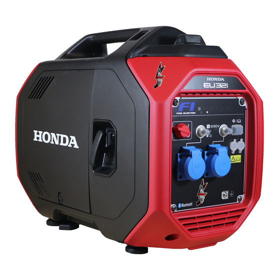
CONTROLS & FEATURES COMPONENT & CONTROL LOCATIONS Use the illustrations on these pages to locate and identify the most frequently used controls. AIR CLEANER FUEL FILLER CAP MAINTENANCE COVER STARTER GRIP SPARK PLUG MAINTENANCE COVER SPARK PLUG GRIP MUFFLER UNDER GRIP FRAME SERIAL NUMBER... - Page 26 CONTROLS & FEATURES IT Type F, G Types INDICATORS AC RECEPTACLES (230V 16A) ECO THROTTLE SWITCH AC CIRCUIT PROTECTORS (16A) ENGINE SWITCH PARALLEL OPERATION OUTLETS GROUND TERMINAL AC RECEPTACLES (230V 16A)
-
Page 27: Controls
CONTROLS & FEATURES CONTROLS Engine Switch ENGINE SWITCH The engine switch controls the ignition system. OFF – Stops the engine. ON – Running position, and for starting with the recoil starter. Starter Grip Pulling the starter grip operates the recoil starter to start the engine. Do not allow the starter grip to snap back against the generator. -
Page 28: Eco Throttle Switch
CONTROLS & FEATURES Eco Throttle Switch The Eco Throttle system automatically reduces engine speed when loads are turned off or disconnected. When appliances are turned on or reconnected, the engine returns to the proper speed to power the electrical load. Each time you push the Eco Throttle Switch, the system turns on and off. -
Page 29: Parallel Operation Outlets
CONTROLS & FEATURES Parallel Operation Outlets These outlets are used for connecting two EU32i generators for parallel operation (see page 46 through 48). A Honda approved parallel cable (optional equipment) is required for parallel operation. This cable can be purchased from your servicing dealer. -
Page 30: Features
CONTROLS & FEATURES FEATURES Ground Terminal The generator ground terminal is connected to the frame of the generator, the metal non-current-carrying parts of the generator, and the ground terminals of each receptacle. Before using the ground terminal, consult a qualified electrician, electrical inspector, or local agency having jurisdiction for local codes or ordinances that apply to the intended use of the generator. -
Page 31: Fuel Level Indicator
CONTROLS & FEATURES Fuel Level Indicator The fuel level indicator is a mechanical device that measures the fuel level in the tank. To provide increased operating time, start with a full tank before operation. Check the fuel level with the generator on a level surface. Always refuel with the engine OFF and cool. -
Page 32: Oil Alert/Check Indicator
CONTROLS & FEATURES Overload Alarm (Indicator) If the generator is overloaded (in excess of 3.2 kVA), or if there is a short circuit in a connected appliance, the overload alarm indicator (red) will come ON. The overload alarm indicator (red) will stay ON, and after about 10 seconds, when an overload or about 5 seconds in case of a short circuit, current to the connected appliance(s) will shut off, and the output indicator (green) will go OFF. -
Page 33: Bluetooth® Function
Smartphone application The Honda “My Generator” smartphone application is for use only with Honda generators equipped with Bluetooth® technology. The application is able to do the following convenient functions: • Remote stop: Can stop the generator engine from a distance •... - Page 34 You may create your own personal password. Please record this password (see page 70). It is very important that you do not forget or lose it. If a password is lost, you must, at your expense, take your generator to an authorized Honda servicing dealer so it can be reset.
-
Page 35: Led Light Patterns
CONTROLS & FEATURES LED Light Patterns OIL ALERT/CHECK INDICATOR OVERLOAD ALARM INDICATOR OUTPUT INDICATOR Status Possible Output Oil Alert/ Overload cause Indicator Check Alarm Indicator Indicator Normal Operating normally Malfunction Inverter unit failure Abnormal Output overcurrent Inverter unit overheat Warning Engine oil low : ON : OFF... -
Page 36: Grip And Under Grip
CONTROLS & FEATURES Grip and Under Grip Use the grip by your hand when lifting the generator. In addition to using the grip, you can lift the generator using the under grip by the other hand if necessary. GRIP UNDER GRIP... -
Page 37: Before Operation
BEFORE OPERATION ARE YOU READY TO GET STARTED? Your safety is your responsibility. A little time spent in preparation will significantly reduce your risk of injury. Knowledge Read and understand this manual. Know what the controls do and how to operate them. -
Page 38: Check The Engine
BEFORE OPERATION To prevent a possible fire, keep the generator at least 1 meter (3 feet) away from building walls, vehicles, and other equipment during operation. Do not place flammable objects close to the engine or exhaust. Before beginning your pre-operation checks, be sure the generator is on a level and firm surface and the engine switch is in the OFF position. - Page 39 BEFORE OPERATION • Limit length of extension cables; 60 m (200 feet) for cables of 1.5 mm (0.0023 ) and 100 m (330 feet) for cables of 2.5 mm (0.0039 in ). Long extension cables will lower usable power due to resistance in the extension cable. •...
-
Page 40: Engine Oil Level Check
BEFORE OPERATION ENGINE OIL LEVEL CHECK Check the engine oil level with the generator on a level surface and the engine stopped. 1. Loosen the maintenance cover screw and remove the maintenance cover. MAINTENANCE COVER MAINTENANCE COVER SCREW 2. Remove the oil filler cap by turning it counterclockwise. Wipe the dipstick clean. -
Page 41: Air Filter Check
BEFORE OPERATION The Oil Alert system will automatically stop the engine before the oil level falls below safe limits. However, to avoid the inconvenience of an unexpected shutdown, check the oil level regularly. AIR FILTER CHECK MAINTENANCE COVER 1. Loosen the maintenance cover screw and remove the maintenance cover. -
Page 42: Safe Operating Precautions
BEFORE OPERATION 8. Reinstall the paper air filter, the guide and the air cleaner cover. 9. Reinstall the maintenance cover, and tighten the maintenance cover screw securely. Operating the engine without the air filters or with a damaged air filter will allow dirt to enter the engine, causing rapid engine wear. -
Page 43: Operation
OPERATION STARTING THE ENGINE To prevent a possible fire, keep the generator at least 1 meter (3 feet) away from building or trailer walls, vehicles, trailers, boats, and other equipment during operation. Do not place flammable objects close to the engine or exhaust. •... - Page 44 OPERATION 3. Pull the starter grip lightly until you feel resistance; then pull briskly in the direction of the arrow as shown. Direction to pull Do not allow the starter grip to snap back against the generator. Return it gently to prevent damage to the starter.
-
Page 45: Stopping The Engine
OPERATION STOPPING THE ENGINE To stop the engine in an emergency, simply turn the engine switch to the OFF position securely. Under normal conditions, use the following procedure. 1. Turn off or disconnect all appliances that are connected to the generator. 2. -
Page 46: Stopping The Engine With Bluetooth® Enabled Smartphone
OPERATION STOPPING THE ENGINE with ® ENABLED SMARTPHONE The engine can be stopped via a Bluetooth® enabled smartphone using a Bluetooth® application. Refer to the Bluetooth® application to check the connection, operation, and for help pairing a smartphone. AC OPERATION If an appliance begins to operate abnormally, becomes sluggish, or stops suddenly, turn it off immediately. - Page 47 OPERATION Connect a RCBO (Residual current circuit breaker with overload protection) of 30 mA ground fault detection and cut-off of less than 0.4 seconds at more than 30 A of output current, if you are using two or more appliance. Follow the instructions provided by each RCBO manufacturer before use.
-
Page 48: Ac Applications
OPERATION 3. Turn on the appliance. If the generator is overloaded (see page 45), or if there is a short circuit in a connected appliance, the overload alarm indicator (red) will go ON. The overload alarm indicator (red) will stay ON, and after about 10 seconds when an overload or about 5 seconds in case of a short circuit, current to the connected appliance(s) will shut off, and the output indicator (green) will go OFF. -
Page 49: Ac Parallel Operation
Honda servicing dealer. During parallel operation, the Eco Throttle switch should be in the same position on both generators. 1. Connect the parallel cable between the two EU32i generators following the instructions supplied with the cable. PARALLEL CABLE (optional equipment) 2. -
Page 50: Ac Parallel Operation Applications
• Never connect different generator models and types. • Use only a Honda approved parallel cable (optional equipment) when connecting two EU32i generators for parallel operation. • Never connect or remove the parallel cable when the generator is running. - Page 51 OPERATION Most appliance motors require more than their rated wattage for startup. Make sure the electrical rating of the tool or appliance does not exceed the maximum power rating of the generator. Maximum power in parallel operation is: 6.4 kVA For continuous operation, do not exceed the rated power.
-
Page 52: Eco Throttle System
OPERATION ECO THROTTLE SYSTEM Each time you push the Eco Throttle Switch, the system turns on and off. With the system in the ON, engine speed is automatically lowered when loads are reduced, turned off, or disconnected. When appliances are turned on or reconnected, the engine returns to the proper speed to power the electrical load. -
Page 53: Standby Power
OPERATION STANDBY POWER Connections to a Building’s Electrical System Connections for standby power to a building’s electrical system must be made by a qualified electrician. The connection must isolate the generator power from utility power, and must comply with all applicable laws and electrical codes. -
Page 54: Special Requirements
OPERATION Special Requirements Do not lay the generator on its side when moving, storing, or operating it. Oil and fuel may leak and damage the engine or your property. There may be applicable laws, local codes, or ordinances that apply to the intended use of the generator. -
Page 55: Servicing Your Generator
Remember that an authorized Honda servicing dealer knows your generator best and is fully equipped to maintain and repair it. To ensure the best quality and reliability, use only new, Honda Genuine parts or their equivalents for repair and replacement. -
Page 56: Maintenance Safety
SERVICING YOUR GENERATOR MAINTENANCE SAFETY Some of the most important safety precautions follow. However, we cannot warn you of every conceivable hazard that can arise in performing maintenance. Only you can decide whether or not you should perform a given task. -
Page 57: Maintenance Schedule
(2) These items should be serviced by your servicing dealer, unless you have the proper tools and are mechanically proficient. Refer to the Honda shop manual for service procedures. (3) For commercial use, log hours of operation to determine proper maintenance intervals. -
Page 58: Engine Oil Change
SERVICING YOUR GENERATOR ENGINE OIL CHANGE Drain the oil while the engine is warm to assure rapid and complete draining. 1. Turn the engine switch to the OFF position (see page 42) to reduce the possibility of fuel leakage. 2. Loosen the maintenance cover screw and remove the maintenance cover (see page 37). -
Page 59: Air Cleaner Service
SERVICING YOUR GENERATOR AIR CLEANER SERVICE Foam Air Filter Cleaning A dirty foam air filter will restrict air flow to the fuel system, reducing engine performance. If you operate the generator in very dusty areas, clean the foam air filter more frequently than specified in the Maintenance Schedule. 1. -
Page 60: Spark Plug Service
SERVICING YOUR GENERATOR SPARK PLUG SERVICE Recommended spark plug: CR6HSB (NGK) To ensure proper engine operation, the spark plug must be properly gapped and free of deposits. An incorrect spark plug can cause engine damage. If the engine is hot, allow it to cool before servicing the spark plug. 1. - Page 61 SERVICING YOUR GENERATOR 4. Inspect the spark plug. Replace it if SIDE ELECTRODE the electrodes are worn or fouled, or SEALING WASHER if the insulator is cracked or chipped. 0.6–0.7 mm Clean the spark plug with a wire (0.024–0.028 in) brush if it is to be reused.
-
Page 62: Spark Arrester Service
SERVICING YOUR GENERATOR SPARK ARRESTER SERVICE If the engine has been running, the muffler will be very hot. Allow the muffler to cool before servicing the spark arrester. Clean the spark arrester as follows: 1. Remove the two 6×15 mm screws, and the rear cover. Remove the two 6 mm screws, two 6×15 mm screws and the muffler protector. - Page 63 SERVICING YOUR GENERATOR 2. Remove the 4 mm screw, and the spark arrester. 4 mm SCREW SPARK ARRESTER 3. Use a brush to remove carbon deposits from the spark arrester screen. Be careful to avoid damaging the screen. The spark arrester must be free of breaks and tears. Replace the spark arrester if it is damaged.
-
Page 64: Storage
STORAGE STORAGE PREPARATION Proper storage preparation is essential for keeping your generator trouble-free and looking good. The following steps will help to keep rust and corrosion from impairing your generator’s function and appearance, and will make the engine easier to start when you use the generator again. Cleaning Wipe the generator with a moist cloth. - Page 65 STORAGE Service according to the table below: STORAGE TIME RECOMMENDED SERVICE PROCEDURE TO PREVENT HARD STARTING Less than 1 month No preparation required. 1 month to 1 year Drain the fuel tank (see page 63). 1 year or more Drain the fuel tank (see page 63). Remove the spark plug.
- Page 66 STORAGE DRAINING THE FUEL TANK Gasoline is highly flammable and explosive. You can be burned or seriously injured when handling fuel. • Stop the engine and let it cool before handling fuel. • Keep heat, sparks, and flame away. • Handle fuel only outdoors. •...
-
Page 67: Engine Oil
STORAGE Engine Oil Change the engine oil (see page 55). Engine Cylinder 1. Remove the spark plug (see page 57). 2. Pour a teaspoon (5 cm ) of clean engine oil into the cylinder. 3. Pull the starter rope several times to distribute the oil in the cylinder. 4. -
Page 68: Removal From Storage
STORAGE REMOVAL FROM STORAGE Check your generator as described in the "BEFORE OPERATION" chapter of this manual (see page 34). If the fuel was drained during storage preparation, fill the fuel tank with fresh gasoline. If you keep a container of gasoline for refueling, be sure that it contains only fresh gasoline. -
Page 69: Transporting
TRANSPORTING An engine that has been running will remain very hot for a period of time. A hot engine and exhaust system can burn you and ignite some material. If the generator has been used, allow it to cool for at least 15 minutes before loading the generator on the transport vehicle. - Page 70 TRANSPORTING To transport the generator, hold the holding part (shaded areas in the figure below). HOLDING PART Avoid a place exposed to direct sunlight when putting the generator on a vehicle. If the generator is left in an enclosed vehicle for many hours, high temperature inside the vehicle could cause fuel to vaporize resulting in a possible explosion.
-
Page 71: Taking Care Of Unexpected Problems
TAKING CARE OF UNEXPECTED PROBLEMS ENGINE WILL NOT START Possible Cause Correction Engine switch is in the OFF position. Turn engine switch to the ON position (see page 40). Out of fuel. Refuel (see page 19). Bad fuel; generator stored without Drain fuel tank (see page 63). -
Page 72: Engine Lacks Power
TAKING CARE OF UNEXPECTED PROBLEMS ENGINE LACKS POWER Possible Cause Correction Air filter restricted. Clean or replace air filter (see page 56). Bad fuel; generator stored without Drain fuel tank (see page 63). treating or draining gasoline, or Refuel with fresh gasoline refueled with bad gasoline. -
Page 73: Technical Information
TECHNICAL INFORMATION SERIAL NUMBER LOCATION QR CODE FRAME SERIAL NUMBER Record the frame serial number and date purchased in the spaces below. You will need this information when ordering parts and when making technical or warranty inquiries. Frame serial number: Date purchased: Entering the frame serial number of the generator is required during the first Bluetooth®... -
Page 74: Specifications
TECHNICAL INFORMATION SPECIFICATIONS Dimensions Model EU32i Type Description code EBKJ Length 571 mm (22.5 in) 596 mm (23.5 in) Width 306 mm (12.0 in) Height 452 mm (17.8 in) Dry mass [weight] 26.5 kg (58.4 lbs) Engine Model GX130 Engine type... - Page 75 TECHNICAL INFORMATION Generator Model EU32i Type F, G, IT AC output Rated voltage 230 V Rated frequency 50 Hz Rated current 11.3 A Rated output 2.6 kVA Maximum output 3.2 kVA...
- Page 76 TECHNICAL INFORMATION Noise Model EU32i Type F, G, IT Sound pressure level at the workstation 73 dB (A) (2006/42/EC) (with Eco throttle ON) Microphone point CONTROL PANEL Center 1.60 m 1.0 m Uncertainty 3 dB (A) Measured sound power level...
- Page 77 TECHNICAL INFORMATION Wiring Diagram (See inside back cover) Abbreviations Wire color code Symbol Part name Black Brown ACCP AC Circuit Protector Green ACOR AC Output Receptacle Gray BASe Bank Angle Sensor Blue Control Panel Block Light blue EcoSw Eco Throttle Switch Light green ECU Ground Orange...
- Page 78 TECHNICAL INFORMATION Receptacle Type Shape Plug GROUND PIN GROUND PIN GROUND PIN...
-
Page 79: Reference Information
です。 The Bluetooth word mark and logos are registered trademarks owned by Bluetooth SIG, Inc., and any use of such marks by Honda Motor Co., Ltd., is under license. Other trademarks and trade names are those of their respective owners. -
Page 80: Wiring Diagram
WIRING DIAGRAM SCHÉMA DE CABLAGE SCHALTPLAN DIAGRAMMA DEI COLLEGAMENTI... -
Page 84: Major Honda Distributor Addresses
Para obtener más información, póngase en contacto con el Centro de información para clientes Honda en la dirección o número de teléfono siguientes: ELENCO DEI MAGGIORI DISTRIBUTORI Honda IN EUROPA Per ulteriori informazioni rivolgersi al Centro informazioni clienti Honda al seguente indirizzo o numero telefonico:... - Page 85 AUSTRIA BULGARIA DENMARK Honda Motor Europe Ltd Premium Motor Ltd TIMA A/S Hondastraße 1 Andrey Lyapchev Blvd no 34 Ryttermarken 10 2351 Wiener Neudorf 1797 Sofia DK-3520 Farum Tel.: +43 (0)2236 690 0 Bulgaria Tel.: +45 36 34 25 50 Fax: +43 (0)2236 690 480 Tel.: +3592 423 5879...
- Page 86 GREECE ITALY POLAND Technellas S.A. Honda Motore Europe Ltd Aries Power Equipment 92 Athinon Ave Via della Cecchignola, 13 Puławska 467 10442 Athens, Greece 00143 Roma 02-844 Warszawa Tel.: +30 210 519 31 10 Tel.: +848 846 632 Tel.: +48 (22) 861 43 01...
- Page 87 SLOVAK REPUBLIC SWEDEN UKRAINE Honda Motor Europe Ltd Honda Motor Europe Ltd filial Dnipro Motor LLC Slovensko, organizačná zložka Sverige 3, Bondarsky Alley, Prievozská 6 821 09 Bratislava Box 31002 - Långhusgatan 4 Kyiv, 04073, Ukraine Tel.: +421 2 32131111 215 86 Malmö...
-
Page 88: "Uk Declaration Of Conformity" Content Outline
Aalst , BELGIUM Date: _______________________ Head of Certification Honda Motor Europe Ltd - Aalst Office *1: see specification page. *1: consulte la página de las especificaciones *2: see original UK Declaration of Conformity. *2: ver Declaración de conformidad UK original *1: voir page de spécifications... -
Page 89: Ec Declaration Of Conformity" Content Outline
Manufacturer Honda Motor Co., Ltd. 2-1-1 Minamiaoyama, Minato-ku, Tokyo, JAPAN Authorized representative and able to compile the technical documentation Honda Motor Europe Ltd - Aalst Office, Wijngaardveld 1 (Noord V), 9300 Aalst, Belgium References to applied standards EN ISO 8528-13:2016... - Page 90 Français. (French) Italiano (Italian) Deutsch (German) Déclaration CE de Conformité Dichiarazione CE di Conformità EG-Konformitätserklärung 1. Le sous signé, *2, de la part du représentant autorisé, déclare 1. Il sottoscritto, *2, in qualità di rappresentante autorizzato, 1. Der Unterzeichner, *2 erklärt hiermit im Namen der que la machine décrit ci-dessous répond à...
- Page 91 Latviešu (Latvian) Magyar (Hungarian) Cestina (Czech) EK-megfelelőségi nyilatkozata ES – Prohlášení o shodě EK atbilstības deklarācija 1. Alulírott *2, a gyártó cég törvényes képviselőjeként 1. Podepsaný *2, jako autorizovaná osoba zde potvrzuje, že stroj 1. *2 ar savu parakstu zem šī dokumenta, autorizētā pārstāvja nyilatkozom, hogy az általunk gyártott gép megfelel az összes, popsaný...
- Page 92 EU32i *00X36Z45 6000* Honda Motor Co., Ltd. 2021 36Z45600 英 仏 独 伊 00X36Z45 6000 Printed in Japan 00X36-Z45-6000...
Need help?
Do you have a question about the EU32i and is the answer not in the manual?
Questions and answers