Honda EU26i Owner's Manual
Hide thumbs
Also See for EU26i:
- Owner's manual (72 pages) ,
- Owner's manual (65 pages) ,
- Owner's manual (69 pages)
Table of Contents
Advertisement
CONTENTS
1.
2.
3.
4.
5.
6.
7.
8.
9.
10.
11.
12.
13.
2
..................................................................
............................................................
................................................................
.................................................................
...........................................................................
.................................................................
...............................................................................
...........................................................
......................................................................
.............................................................................
..........................................................................
...................................................
.......................................................
................................
. 3
. 6
. 8
. 9
. 13
. 18
. 25
. 38
. 40
. 54
. 56
. 58
. 62
. 68
Advertisement
Table of Contents

Related Manuals for Honda EU26i


Summary of Contents for Honda EU26i
- Page 1 High altitude operation GENERATOR USE ................25 STOPPING THE ENGINE ..............38 MAINTENANCE ................40 TRANSPORTING/STORAGE ............54 TROUBLESHOOTING ............... 56 SPECIFICATIONS ................58 WIRING DIAGRAM ................62 MAJOR Honda DISTRIBUTOR ADDRESSES ........ . 68...
- Page 2 Honda EU26i·EU30is OWNER’S MANUAL The‘‘e-SPEC’’mark symbolizes environmentally responsible technologies applied to Honda power equipment, which contains our wish to ‘‘preserve nature for generations to come.’’...
- Page 3 All information in this publication is based on the latest product information available at the time of approval for printing. Honda Motor Co., Ltd. reserves the right to make changes at any time without notice and without incurring any obligation.
-
Page 4: Safety Instructions
SAFETY INSTRUCTIONS To ensure safe operation Honda generator is designed to give safe and dependable service if operated according to instructions. Read and understand the Owner’s Manual before operating the generator. Failure to do so could result in personal injury or equipment damage. - Page 5 To ensure safe operation Gasoline is extremely flammable and explosive under certain conditions. Refuel in a well ventilated area with the engine stopped. Keep away from cigarette, smoke and sparks when refueling the generator. Always refuel in a well-ventilated location. Wipe up spilled gasoline at once.
- Page 6 To ensure safe operation Always make a pre-operation inspection (page ) before you start the engine. You may prevent an accident or equipment damage. Place the generator at least 1 m (3 ft) away from buildings or other equipment during operation. Operate the generator on a level surface.
-
Page 7: Safety Label Locations
These labels warn you of potential hazards that can cause serious injury. Read the labels and safety notes and precautions described in this manual carefully. If a label comes off or becomes hard to read, contact your Honda dealer for a replacement. [For European model: G, GW, B, F types]... - Page 8 [For Australian model: U type]...
-
Page 9: Ce Mark And Noise Label Locations
CE mark and noise label locations [G, GW, B, F types only] NOISE LABEL [Example: EU30is NOISE LABEL] CE MARK Maximum ambient temperature Manufacturer and address Performance class IP code Maximum altitude Dry weight [Example: EU30is CE MARK]... -
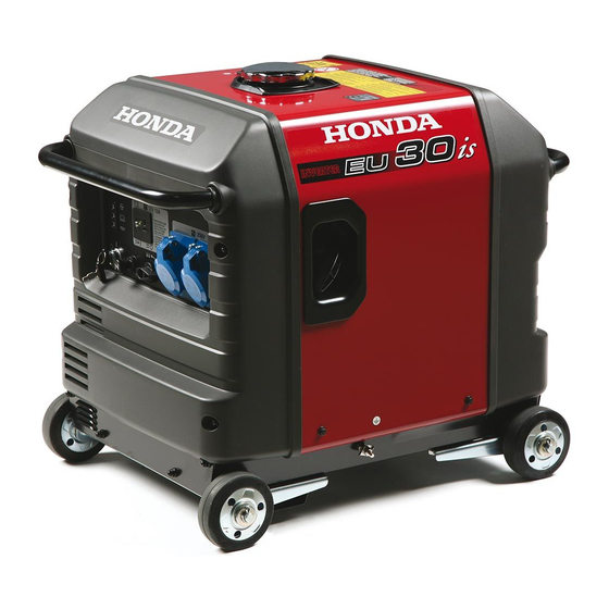
Page 10: Component Identification
COMPONENT IDENTIFICATION STAND TYPE FRONT COVER STARTER GRIP FRONT HANDLE PIPE GROUND TERMINAL CONTROL PANEL WHEEL TYPE... - Page 11 MUFFLER FUEL FILLER CAP REAR HANDLE PIPE SPARK PLUG CAP OIL FILLER CAP AIR CLEANER OIL DRAIN PLUG FRAME SERIAL NUMBER OIL MAINTENANCE COVER LEFT SIDE MAINTENANCE COVER Record the frame serial number in the space below. You will need this serial number when ordering parts.
-
Page 12: Control Panel
CONTROL PANEL EU26i/EU30is: F, G, GW types PARALLEL OPERATION SOCKET DC CIRCUIT PROTECTOR AC OUTPUT INDICATOR LIGHT DC RECEPTACLE AC OVERLOAD INDICATOR LIGHT OIL ALERT INDICATOR LIGHT ENGINE SWITCH CHOKE KNOB FUEL VALVE LEVER AC RECEPTACLES ECO THROTTLE SWITCH EU26i/EU30is: B type... - Page 13 Eco Throttle ECO: Engine speed is kept at idle automatically when the electrical appliance is disconnected and it returns to the proper speed by the electrical load when electrical appliance is connected. This position is recommended to minimize the fuel consumption while in operation. When high electrical load appliances is connected simultaneously, turn the Eco Throttle switch to the OFF position to reduce voltage changes.
-
Page 14: Pre-Operation Check
PRE-OPERATION CHECK Be sure to check the generator on a level surface with the engine stopped. Check the engine oil level. Using nondetergent oil or 2-stroke engine oil could shorten the engine’s service life. Use high-detergent, premium quality 4-stroke engine oil, certified to meet or exceed U.S. - Page 15 Open the oil maintenance cover. Remove the oil filler cap, and wipe the dipstick with a clean rag. Check the oil level by inserting the dipstick in the filler hole without screwing it in. If the oil level is below the end of the dipstick, refill with recommended oil up to the top of the oil filler neck.
- Page 16 Check the fuel level. If the fuel level is low, refill to the shoulder of the fuel strainer. After refueling, tighten the fuel filler cap securely. Use automotive unleaded gasoline with a Research Octane Number of 91 or higher (a Pump Octane Number of 86 or higher). Never use stale or contaminated gasoline or an oil/gasoline mixture.
- Page 17 Gasolines containing alcohol If you decide to use a gasoline containing alcohol (gasohol), be sure it’s octane rating is at least as high as that recommended by Honda. There are two types of ‘‘gasohol’’: one containing ethanol, and the other containing methanol.
- Page 18 Check the air cleaner. Check the air cleaner elements to be sure they are clean and in good condition. Open the left side maintenance cover. Unsnap the four clips, remove the air cleaner cover, remove the foam element from the air cleaner cover, and check the both elements.
-
Page 19: Starting The Engine
STARTING THE ENGINE Electric starting (EU30is only) When starting the generator after adding fuel for the first time, after long-term storage, or after running out of fuel, turn the fuel valve lever to the ‘‘ON’’ position, then wait for 10 to 20 seconds before starting the engine. - Page 20 Turn the engine switch to the START position and hold it there until the engine starts. START ENGINE SWITCH Do not use the starter motor for more than 5 seconds. If the engine fails to start, release the key, and wait at least 10 seconds before operating the starter motor again.
- Page 21 Push the choke knob to the OPEN position as the engine warms up. OPEN CHOKE KNOB...
- Page 22 Manual starting When starting the generator after adding fuel for the first time, after long-term storage, or after running out of fuel, turn the fuel valve lever to the ‘‘ON’’ position, then wait for 10 to 20 seconds before starting the engine. Before starting the engine disconnect any load from the AC receptacle.
- Page 23 Turn the engine switch to the ON position. EU30is ENGINE SWITCH EU26is ENGINE SWITCH...
- Page 24 Pull the starter grip lightly until you feel resistance, then pull the starter grip briskly toward the arrow as shown below. Do not allow the starter grip to snap back. Return it slowly by hand. Do not let the starter rope rub against the generator body or the rope will wear out prematurely.
- Page 25 If you always operate the generator at altitudes higher than 1,500-meter (5,000 feet) above sea level, have your authorized Honda dealer perform these carburetor modifications. Even with suitable carburetor jetting, engine horsepower will decrease approximately 3.5% for each 300-meter (1,000-foot) increase in altitude.
-
Page 26: Generator Use
GENERATOR USE Be sure to ground the generator when the connected equipment is grounded. Connections for standby power to a building’s electrical system must be made by a qualified electrician and must comply with all applicable laws and electrical codes. Improper connections can allow electrical current from the generator to backfeed into the utility lines. - Page 27 Limit operation requiring maximum power (see pages ) to 30 minutes. For continuous operation, do not exceed the rated power (see pages In either case, the total wattage of all appliances connected must be considered. Do not exceed the current limit specified for any one receptacle. Do not connect the generator to a household circuit.
- Page 28 The DC receptacle can be used while the AC power is in use. If you use both at the same time, be sure not to exceed the total power for AC and DC. (See page The C type cannot be used for both AC and DC simultaneously. Most appliance motors require more than their rated wattage for startup.
- Page 29 AC applications Start the engine and make sure the Output indicator (green) comes Confirm that the appliance to be used is switched off, and plug in the appliance. OUTPUT INDICATOR LIGHT (GREEN) OVERLOAD INDICATOR LIGHT (RED) Substantial overloading that continuously lights the overload indicator light (red) may damage the generator.
- Page 30 When an electric motor is started, both the Overload indicator (red) and the Output indicator (green) may go on simultaneously. This is normal if the Overload indicator (red) goes off after about five (5) seconds. If the Overload indicator (red) stays on, consult your Honda generator dealer.
- Page 31 These are the terminals into which the special cable/receptacle is inserted for parallel operation. Always use only the special cable/receptacle for parallel operation. EU26i-B, F, G, U types and EU30is-B, F, U type: The special cable/receptacle is sold separately. Please order the special cable/receptacle from the shop where you purchased the unit or from a service station.
- Page 32 In parallel operation, the obtainable output differs according to the models. EU26i: 4.8 kVA EU30is: 5.6 kVA Depending on the equipment to be used, an overload may be caused, the overload indicator light (red) may light, and it may become impossible to take out any more electric power.
- Page 33 Be sure to ground the generator when the connected equipment is grounded. GROUND TERMINAL Start each engine according to ‘‘STARTING THE ENGINE’’. When the output indicator light (green) does not light and the overload indicator light (red) lights instead, set the engine switch to STOP, stop the engine once, and then start the engine again.
- Page 34 Switch on the equipment to be used. The output indicator light (green) will light. In case of normal operation In case of overload operation or short-circuit OUTPUT INDICATOR LIGHT OUTPUT INDICATOR LIGHT (RED) (GREEN) In case of overload operation (refer to page ) or when trouble occurs for the equipment being used, the output indicator light (green) will go out, the overload indicator light (red) will light...
- Page 35 (do not use the AC output) EU26i 10 A approximately 3.3 A EU30is 12 A approximately 4 A Connect the charging cable to the DC receptacle of the generator and then to the battery terminals. DC CIRCUIT PROTECTOR CHARGING CABLE (SOLD SEPARATELY) (Example: EU26i)
- Page 36 To prevent the possibility of creating a spark near the battery, connect charging cable first to the generator, then to the battery. Disconnect cable first at the battery. Before connecting charging cable to a battery that is installed in a vehicle, disconnect the vehicles grounded battery cable.
- Page 37 Start the engine. The DC receptacle may be used while the AC power is in use. An overload DC circuit will trip the DC circuit protector (push button comes out). If this happens, wait a few minutes before pushing in the circuit protector to resume operation.
- Page 38 Oil alert system The Oil Alert system is designed to prevent engine damage caused by an insufficient amount of oil in the crankcase. Before the oil level in the crankcase falls below a safe limit, the Oil Alert system will automatically shut down the engine (the engine switch will remain in the ON position).
-
Page 39: Stopping The Engine
To stop the engine in an emergency, turn the engine switch to the OFF position. IN NORMAL USE: Switch off the connected equipment and pull the inserted plug. In parallel operation Turn the engine switch to the OFF position. EU30is ENGINE SWITCH EU26i ENGINE SWITCH... - Page 40 Turn the fuel valve lever to the OFF position. FUEL VALVE LEVER When parallel operation has been executed, remove the special cable/receptacle for parallel operation. SPECIAL CABLE/RECEPTACLE FOR PARALLEL OPERATION...
-
Page 41: Maintenance
Service more frequently when used in dusty areas. These items should be serviced by your servicing dealer, unless you have the proper tools and are mechanically proficient. Refer to Honda shop manual for service procedures. For commercial use, log hours of operation to determine proper maintenance... - Page 42 CHANGING OIL Drain the oil while the engine is still warm to assure rapid and complete draining. Open and remove the oil maintenance cover. Remove the oil filler cap and oil drain plug to drain the oil. Install the oil drain plug, and tighten it securely. Refill with the recommended oil (see page ) and check the oil level.
- Page 43 AIR CLEANER SERVICE A dirty air cleaner will restrict air flow to the carburetor. To prevent carburetor malfunction, service the air cleaner regularly. Service more frequently when operating the generator in extremely dusty areas. Do not use gasoline or low flash point solvents for cleaning. They are flammable and explosive under certain conditions.
- Page 44 Soak the foam element in clean engine oil and squeeze out the excess oil. The engine will smoke during initial startup if too much oil is left in the foam element. Reinstall the foam element to the air cleaner cover. Paper element: If the paper element is dirty, replace it with a new one.
- Page 45 FUEL SEDIMENT CUP SERVICE Gasoline is extremely flammable and is explosive under certain conditions. Do not smoke or allow flames or sparks in the area. The filter prevents dirt or water which may be in the fuel tank from entering the carburetor. If the engine has not been run for a long time, the filter should be cleaned.
- Page 46 Remove the sediment cup by turning it counterclockwise. Clean the sediment cup, rubber gasket, and filter in nonflammable or high flash point solvent. Reassemble the filter, rubber gasket, and sediment cup. Tighten securely. Reinstall the air cleaner base, and connect the breather gas hose with the air cleaner base.
- Page 47 SPARK PLUG SERVICE RECOMMENDED SPARK PLUG: BPR5ES (NGK) W16EPR-U (DENSO) To ensure proper engine operation, the spark plug must be properly gapped and free of deposits. Open the left side maintenance cover. Loosen the cover screw and remove the spark plug inspection cover. SPARK PLUG INSPECTION COVER COVER SCREW Remove the spark plug cap.
- Page 48 Visually inspect the spark plug. Discard it if the insulator is cracked or chipped. Clean the spark plug with a wire brush if it is to be reused. Measure the plug gap with a feeler gauge. Correct as necessary by carefully bending the side electrode. The gap should be: 0.70 0.80 mm (0.028 0.031 in) PLUG GAP...
- Page 49 SPARK ARRESTER MAINTENANCE If the generator has been running, the muffler will be very hot. Allow it to cool before proceeding. The spark arrester must be serviced every 100 hours to maintain its efficiency. Remove the four 6 mm cap nuts, and remove the rear cover. Remove the four 6 mm bolts and the earth washer (C type only), and remove the upper muffler protector.
- Page 50 Remove the three 5 mm bolts, and remove the exhaust tail pipe and the spark arrester. EXHAUST TAIL PIPE SPARK ARRESTER 5 mm BOLTS Use a brush to remove carbon deposits from the spark arrester screen. Inspect the spark arrester screen for holes or tears. Replace if necessary.
- Page 51 Reinstall the lower muffler protector, the rear under plate, and the rear handle pipe. Reinstall the lower muffler protector inside the hook securely. LOWER MUFFLER PROTECTOR HOOK LOWER MUFFLER PROTECTOR HOOK REAR UNDER PLATE REAR HANDLE PIPE Reinstall the upper muffler protector and the rear cover. When installing the rear cover, carefully fit the rubber drip guard around the oil filler neck and oil drain neck.
- Page 52 FUSE REPLACEMENT (EU30is only) If the fuse is blown, the starter motor will not work until it is replaced. Turn the engine switch to the OFF position. Remove the four 6 mm cap nuts and the front cover. FRONT COVER 6 mm CAP NUTS Remove the fuse holder cover and replace the fuse.
- Page 53 BATTERY REMOVAL/INSTALLATION (EU30is only) Batteries produce explosive gases: If ignited, and explosion can cause serious injury or blindness. Provide adequate ventilation when charging. CHEMICAL HAZARD: Battery electrolyte contains sulfuric acid. Contact with eyes or skin, even through plathins, may cause severe burns.
- Page 54 Installation: Make sure that the engine switch is turned OFF. Connect the battery positive ( ) cable to the battery positive ( ) terminal, then the battery negative ( ) cable to the battery negative ( ) terminal. Tighten the bolts and nuts securely. Install the battery holder band.
-
Page 55: Transporting/Storage
TRANSPORTING/STORAGE To prevent fuel spillage when transporting or during temporary storage, the generator should be secured upright in its normal operating position, with the engine switch OFF. The fuel valve lever should be turned OFF. When transporting the generator: Do not overfill the tank. Do not operate the generator while it is on a vehicle. - Page 56 Once a month, recharge the battery. (EU30is only) Change the engine oil. Remove the spark plug and pour about a tablespoon of clean engine oil into the cylinder. Crank the engine several revolutions to distribute the oil, then reinstall the spark plug. Slowly pull the starter grip until resistance is felt.
-
Page 57: Troubleshooting
To check: If the engine still Turn off the fuel valve does not start, lever and loosen the take the drain screw. generator to an Turn on the fuel valve authorized lever. Fuel should flow Honda dealer. from the drain. - Page 58 Appliance does not operate: Is the Output indicator ON? Take the Is the Overload generator to an indicator ON? authorized Honda dealer. Check the Take the electrical NO DEFECTS generator to an appliance or authorized equipment for Honda dealer. any defects.
-
Page 59: Specifications
SPECIFICATIONS Dimensions and Weight Model EU26i Description code EZGE Length (Stand type) 655 mm (25.8 in) (Wheel type) 655 mm (25.8 in) Width (Stand type) 445 mm (17.5 in) (Wheel type) 480 mm (18.9 in) Height (Stand type) 555 mm (21.9 in) (Wheel type) 570 mm (22.4 in) - Page 60 Noise Model EU26i Type F, G, GW, B Sound pressure level (Lp ) 75 dB According to 98/37/EC Microphone point CONTROL PANEL Center 1.60 m 1.0 m Guaranteed sound power level 90 dB ) Tested by 2000/14/EC Specifications are subject to change without notice.
- Page 61 Dimensions and Weight Model EU30is Description code EZGF Length (Stand type) 655 mm (25.8 in) (Wheel type) 655 mm (25.8 in) Width (Stand type) 445 mm (17.5 in) (Wheel type) 480 mm (18.9 in) Height (Stand type) 555 mm (21.9 in) (Wheel type) 570 mm (22.4 in) Dry weight...
- Page 62 Noise Model EU30is Type F, G, GW, B Sound pressure level (Lp ) 76 dB According to 98/37/EC Microphone point CONTROL PANEL Center 1.60 m 1.0 m Guaranteed sound power level 91 dB ) Tested by 2000/14/EC Specifications are subject to change without notice.
-
Page 63: Wiring Diagram
WIRING DIAGRAM AC, NF AC Noise Filter ACOR AC Output Receptacle Battery Charge Winding Composite Socket Circuit Protector Control Panel Block DC, D DC Diode DC, NF DC Noise Filter DC, P DC Protector DC, W DC Winding DCOR DC Output Receptacle EcoSw Eco Throttle Switch Engine Block... - Page 64 BLACK YELLOW BLUE GREEN WHITE BROWN LIGHT GREEN GRAY LIGHT BLUE ORANGE PINK ENGINE SWITCH EU26i EU30is START ECOTHROTTLE SWITCH ECOTHROTTLE...
- Page 65 EU26i: G, GW, B, F...
- Page 66 EU26i: U...
- Page 67 EU30is: G, GW, B, F...
- Page 68 EU30is: U...
- Page 69 RECEPTACLE Shape Type G, GW...
-
Page 70: Major Honda Distributor Addresses
Honda Power Equipment Sweden AB Västkustvägen 17 Tel: 040-600 23 00 202 15 Malmö, Fax: 040-600 23 19 Sweden Honda Produtos De Força, Portugal, S.A. Lugar da Abrunheira Tel: 351-1-9150374 S. Pedro de Penaferrim Fax: 351-1-9111021 2710 Sintra, Portugal Berema A/S... - Page 71 2040 Buda-rs, Kamaraerdei-t 3. Tel: 23-444-971 Hungary Fax: 23-444-972 For Australian NAME OF FIRM (COMPANY) ADDRESS TEL: FAX: Honda Australia Motorcycle and Power 1954-1956 Hume Highway Tel: (03) 9270 1111 Equipment Pty. Ltd Campbelifield Victoria 3061 Fax: (03) 9270 1133...
Need help?
Do you have a question about the EU26i and is the answer not in the manual?
Questions and answers