
Related Manuals for Hewlett Packard Enterprise Brocade 32Gb/12 2SFP+


Summary of Contents for Hewlett Packard Enterprise Brocade 32Gb/12 2SFP+
- Page 1 Brocade 32Gb Fibre Channel SAN Switch Module for HPE Synergy User Guide Part Number: P11206-001 Published: December 2018 Edition: 1...
- Page 2 Packard Enterprise products and services are set forth in the express warranty statements accompanying such products and services. Nothing herein should be construed as constituting an additional warranty. Hewlett Packard Enterprise shall not be liable for technical or editorial errors or omissions contained herein.
-
Page 3: Table Of Contents
Contents Overview....................6 Brocade 32Gb FC Switch Module features ..................6 Component identification....................6 Port side of the Brocade 32Gb FC Switch Module..........7 Internal ports summary.......................7 Brocade 32Gb FC Switch Module redundancy ..............7 Brocade 32Gb FC Switch Module models and licensing........... 8 ISL trunking groups........................8 Supported optional software...................... - Page 4 SAN Switch related documentation.................... 30 HPE Synergy frame related documentation ................30 Document conventions and symbols..................31 Websites............................. 32 Support and other resources...............33 Accessing Hewlett Packard Enterprise Support................. 33 Accessing updates........................33 Customer self repair........................34 Remote support.......................... 34 Warranty information........................34 Regulatory information........................35 Documentation feedback......................
- Page 5 Q..............................44 R..............................45 S..............................45 T..............................46 U..............................46 W..............................46 Z..............................47...
-
Page 6: Overview
Overview The Brocade 32Gb Fibre Channel SAN Switch Module for HPE Synergy (Brocade 32Gb FC Switch Module) is an FC switch that supports link speeds of up to 32 Gbps. The Brocade 32Gb FC Switch Module can operate in a fabric containing multiple switches or it can operate as the only switch in a fabric. NOTE: In this document, the Brocade 32Gb FC Switch Module refers to those Brocade FC switch modules compatible with the HPE Synergy frame only. -
Page 7: Port Side Of The Brocade 32Gb Fc Switch Module
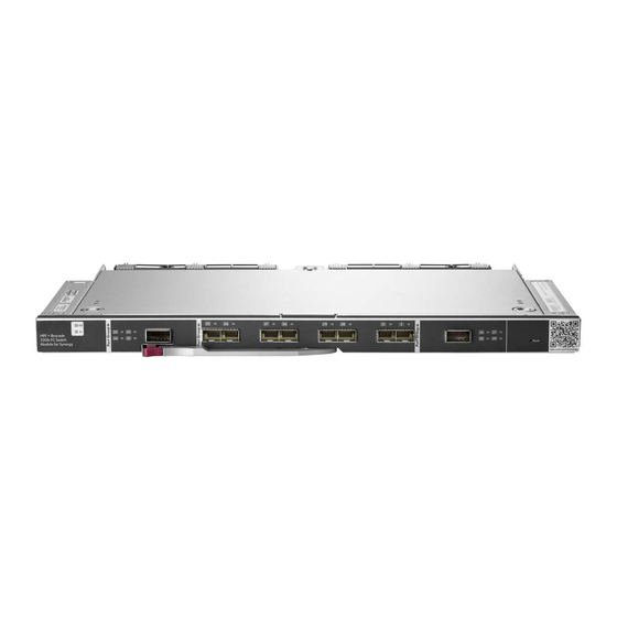
Figure 1: Brocade 32Gb FC Switch Module components 1. Midplane connector 2. UID LED 3. Health LED 4. Installation handle 5. Reset button Port side of the Brocade 32Gb FC Switch Module Figure 2: External ports on page 7 identifies the Brocade 32Gb FC Switch Module external ports (ports 32 through 35, ports 25 through 31 with port 0, and ports 36 through 39). -
Page 8: Brocade 32Gb Fc Switch Module Models And Licensing
• Redundant power and cooling • Redundant Converged Infrastructural Managers (CIM) to run OneView for HPE Synergy frame management and monitoring the switch. HPE OneView does not manage but monitors the Brocade 32Gb FC Switch Module. Brocade 32Gb FC Switch Module models and licensing The Brocade 32Gb FC Switch Module is available in various models that complement existing HPE product lines. -
Page 9: Supported Sfp Transceiver Options
NOTE: • Availability of optional components may change. • Most licenses mentioned below are available as both E-Delivery and physical, with E-Delivery as the default option. Table 1: Optional software Option Brocade 32Gb Fibre Channel SAN Switch Module Power Pack+ E-LTU for HPE Synergy Brocade 32Gb Fibre Channel SAN Switch Module 8-port Upgrade E-LTU for HPE Synergy... - Page 10 Table 4: Optical cables Option QSFP to 4xLC Breakout Cables HPE Premier Flex MPO to 4xLC 5 m Cable HPE Premier Flex MPO to 4xLC 15 m Cable HPE Premier Flex MPO to 4xLC 30 m Cable HPE Premier Flex MPO to 4xLC 50 m Cable OM4 MPO/MPO Multi-mode Cables HPE Premier Flex MPO/MPO OM4 12f 1 m Cable HPE Premier Flex MPO/MPO OM4 12f 2 m Cable...
- Page 11 Table 5: Optic, speed, cable, and distance data transmission ranges Transceiver Form Speed Multimode media Single mode type factor media 9 µm 50 µm (OM3) 50 µm (OM4) SFP+ 32 Gbps 70 m (230 ft) 100 m (328 ft) SFP+ 8 Gbps 150 m (492 ft) 190 m (623 ft)
-
Page 12: Setup
Setup Kit contents The Brocade 32Gb FC Switch Module kit contains: • Brocade 32Gb Fibre Channel SAN Switch Module for HPE Synergy Quick Start Instructions • One of the following switch models: ◦ Brocade 32Gb/12 2SFP+ Fibre Channel SAN Switch Module for HPE Synergy ◦... -
Page 13: Installing The Brocade 32Gb Fc Switch Module
• The air vents on the enclosure are not blocked or restricted. • The ambient air temperature at the front of the enclosure does not exceed 43°C (109.4°F) while the switch is operating. IMPORTANT: The dust covers that ship with your Brocade 32Gb FC Switch Module must be inserted into any ports where SFPs are not installed, to help contain air flow in the Synergy frame. -
Page 14: Hpe Synergy Frame Link Module Power Verification
HPE Synergy Frame Link Module. IMPORTANT: Hewlett Packard Enterprise recommends reading the appropriate HPE Synergy 12000 Frame Setup and Installation Guide and the HPE OneView User Guide for HPE Synergy. -
Page 15: Set The Switch Ethernet Ip Address
1. Health LED 2. UID LED 3. QSFP Ports 32–35 LED 4. SFP Ports 25 and 26 LED 5. SFP Ports 27 and 28 LED 6. SFP Ports 29 and 30 LED 7. SFP Ports 31 and 0 LED 8. QSFP Ports 36–39 LED 9. -
Page 16: Setting The Ip Address Manually
4. Navigate to General section of the Interconnect screen and document the DHCP assigned address. 5. Verify the IP address using a SSH login to the switch. Setting the IP address manually Procedure 1. Open a web browser and connect to the HPE OneView. 2. -
Page 17: Firmware Update
7. Verify the IP address as described in section Using external DHCP on page 15. Firmware update Hewlett Packard Enterprise generally recommends running the latest firmware release. For information on the latest supported, target path, and minimum required versions of firmware, see the B-series FC Switch connectivity stream document at http://www.hpe.com/storage/spock. -
Page 18: Connecting To The Cli
• SFP transceivers and compatible optical cables, as required • Access to an SFTP/SCP server for backing up the switch configuration (optional) Connecting to the CLI Make an Ethernet connection and log in to the Brocade 32Gb FC Switch Module: Procedure 1. -
Page 19: Verifying Installed Licenses
For example: switchName:admin> date 101614302018 Tue Oct 16 14:30:00 UTC 2018 switchName:admin> date Tue Oct 16 18:26:30 UTC 2018 For details about changing time zones, see the tsTimeZone command in the latest version of the Fabric OS Command Reference Guide. Verifying installed licenses To determine the type of licensing included with your Brocade 32Gb FC Switch Module, enter licenseshow at the command prompt, as in the following example:... -
Page 20: Disabling And Enabling A Switch
Disabling and enabling a switch By default, the switch is enabled after power on and after the diagnostics and switch initialization routines have completed. You can disable and re-enable the switch as necessary. To disable a switch: Procedure 1. If you have not already done so, connect to the switch and log in as admin. 2. -
Page 21: Dpod Commands
To initiate DPOD, use the licensePort command, as described in DPOD commands on page 21. IMPORTANT: For the Brocade 32Gb FC Switch Module, DPOD works only if the compute module is installed with an HBA present. A compute module that does not have a functioning HBA is not treated as an active link for the purpose of initial POD port assignment. -
Page 22: Backing Up The Configuration
ports assigned to the base switch allowance: 1, 6, 11, 12, 25, 26, 27, 29, 36*, 37* 38*, 39* ports assigned to the Ports on Demand license: 0*, 2, 3, 4, 5, 7, 8, 9, 10, 28 30*, 31*, 32, 33, 34, 35 ports that are not assigned: 13, 14, 15, 16, 17, 18, 19, 20, 21, 22 23, 24... -
Page 23: Managing The Brocade 32Gb Fc Switch Module
Managing the Brocade 32Gb FC Switch Module Management features The management tools built into the Brocade 32Gb FC Switch Module can be used to monitor fabric topology, port status, physical status, and other information used for performance analysis and system debugging. -
Page 24: Diagnostic Tests
Figure 6: SFP transceiver - pull tab To install a SFP/QSFP transceiver: 1. For transceivers with bails, make sure the bail is in the unlocked position. 2. Orient the transceiver with the appropriate port. 3. Insert the transceiver into the port until it clicks. 4. -
Page 25: Powering On And Off
Powering on and off The Brocade 32Gb FC Switch Module power is provided by the frame. The Brocade 32Gb FC Switch Module runs POST by default each time power to the enclosure is turned on. The POST process can last up to three minutes. -
Page 26: Port Link Status Led Patterns
LED name LED color Status of hardware Recommended action Flashing green (on 1 One or both of the Check environmental second, off 1 second) following are true: conditions, error log, Port Status LEDs, • One or more transceivers, cables, and environmental ranges loopback plugs. -
Page 27: Post And Boot Specifications
LED name LED color Status of hardware Recommended action Slow-flashing amber Port is disabled as a result of Enable the port using the (on 1 second, off 1 diagnostics or portDisable portEnable command; if the second) command. If the LEDs for all ports LEDs for all ports are slow- are slow-flashing amber, the switch flashing amber, enable the... -
Page 28: Interpreting Post Results
• Unicast routing tables are constructed • Normal port operation is enabled Interpreting POST results To determine whether POST completed successfully and whether any errors were detected: Procedure 1. Verify the Brocade 32Gb FC Switch Module LEDs indicate all components are healthy. For a description and interpretation of LED patterns, see Table 7: Port link status LED patterns on page 26. - Page 29 17. Verify the switch is joined to the fabric and all connected devices are logged in to the switch by entering: switchshow 18. Save the configuration file. IMPORTANT: Hewlett Packard Enterprise recommends upgrading all switches in the enclosure to the latest available firmware. Check http://www.hpe.com for updates. Managing the Brocade 32Gb FC Switch Module...
-
Page 30: Resources And Other Information
Resources and other information Related information This guide provides information about setting up and configuring the Brocade 32Gb Fibre Channel SAN Switch Module for HPE Synergy. Throughout this guide the short product name, Brocade 32Gb FC Switch Module is used. The following documents contain related information: •... -
Page 31: Document Conventions And Symbols
Document conventions and symbols Table 8: Document conventions Convention Element Black text: Table 8: Document Cross-reference links and e-mail conventions on page 31 addresses Black, underlined text: http:// website addresses www.hpe.com Bold text • Keys that are pressed • Text typed into a GUI element, such as a box •... -
Page 32: Websites
Websites General websites Hewlett Packard Enterprise Information Library www.hpe.com/info/EIL Single Point of Connectivity Knowledge (SPOCK) Storage compatibility matrix www.hpe.com/storage/spock Storage white papers and analyst reports www.hpe.com/storage/whitepapers For additional websites, see Support and other resources. Product information websites HPE Synergy Composable Systems hpe.com/info/synergy... -
Page 33: Support And Other Resources
Accessing Hewlett Packard Enterprise Support • For live assistance, go to the Contact Hewlett Packard Enterprise Worldwide website: http://www.hpe.com/assistance • To access documentation and support services, go to the Hewlett Packard Enterprise Support Center website: http://www.hpe.com/support/hpesc Information to collect •... -
Page 34: Customer Self Repair
Customer self repair Hewlett Packard Enterprise customer self repair (CSR) programs allow you to repair your product. If a CSR part needs to be replaced, it will be shipped directly to you so that you can install it at your convenience. -
Page 35: Regulatory Information
Documentation feedback Hewlett Packard Enterprise is committed to providing documentation that meets your needs. To help us improve the documentation, send any errors, suggestions, or comments to Documentation Feedback (docsfeedback@hpe.com). When submitting your feedback, include the document title, part number, edition, and publication date located on the front cover of the document. -
Page 36: Electrostatic Discharge And Grounding Recommendations
Use conductive field service tools. • Use a portable field service kit with a folding static-dissipating work mat. If you do not have any of the suggested equipment for proper grounding, have an Hewlett Packard Enterprise authorized reseller install the part. NOTE: For more information on static electricity, or for assistance with product installation, contact your Hewlett Packard Enterprise authorized reseller. -
Page 37: San Switch Technical Specifications
SAN Switch technical specifications General specifications Table 9: General specifications on page 37 lists general specifications for the Brocade 32Gb FC Switch Module. Table 9: General specifications Specification Description Configurable port types F_Port, N_Port, D_Port, and E_Port Media types SFP: Support for speeds of 4/8/16/32Gb with short wave SFPs up to 500m (1,640 ft.) and support for speeds of 4/8/16/32Gb with long wave SFPs up to 10 QSFP: Support for speeds of 4/8/16/32Gb x 4 with... -
Page 38: Environmental Requirements
Dimension Measurement Depth 1.082 in (27.48 mm) Weight 2.99 kg (6.6 lbs) Environmental requirements To ensure proper operation, the switch must not be subjected to environmental conditions beyond those for which it was tested. The ranges specified in Table 11: Environmental requirements on page 38 list the acceptable environment for both operating and non-operating conditions. -
Page 39: Glossary
Glossary This glossary defines terms used in this guide or related to this product. It is not a comprehensive glossary of computer terms. alias server A fabric software facility that supports multicast group management. Application programming interface. A defined protocol that allows applications to interface with a set of services. - Page 40 • Hardware: The number, type, and arrangement of components that make up a system or network. • Software: The set of parameters that guide switch operation. May include general system parameters, IP address information, domain ID, and other information. Modifiable by any login with administrative privileges.
- Page 41 EIA rack A storage rack that meets the standards set by the Electronics Industry Association. enabled zone configuration The currently enabled configuration of zones. Only one configuration can be enabled at a time. See also zone on page 47, and zone configuration on page 47. end-to-end flow control A facility that governs flow of class 1 and class 2 frames between N_Ports.
- Page 42 FLOGI The process by which an N_Port determines whether a fabric is present and, if so, exchanges service parameters with it. See also PLOGI on page 44. frame The FC structure used to transmit data between ports. Consists of a start-of-frame delimiter, header, optional headers, data payload, cyclic redundancy check, and end-of-frame delimiter.
- Page 43 K28.5 A special 10-bit character that indicates the beginning of a transmission word that performs FC control and signaling functions. The first seven bits are the common pattern. kernel flash Flash (temporary) memory connected to the peripheral bus of the processor and visible within the processor's memory space.
- Page 44 NL_Port Node loop port. A node port that has arbitrated loop capabilities. Used to connect an equipment port to the fabric in a loop configuration through an FL_Port. See also node on page 44. node An FC device that contains an N_Port or NL_Port. non-participating mode A mode in which an L_Port in a loop is inactive and cannot arbitrate or send frames, but can retransmit any received transmissions.
- Page 45 R_A_TOV Resource allocation time-out value. The maximum time a frame can be delayed in the fabric and still be delivered. RAID Redundant Array of Independent Disks. A collection of disk drives that appear as a single volume to the server and are fault tolerant through mirroring or parity checking. request rate The rate at which requests arrive at a servicing entity.
- Page 46 switch Hardware that routes frames according to FC protocol and is controlled by software. switch port A port on a switch. Switch ports can be E_Ports, F_Ports, or N_Port. short-wavelength. A type of fiber optic cabling that is based on 850 mm lasers and supports link speeds up to 32 Gbps.
- Page 47 zone A set of devices and hosts attached to the same fabric and configured as being in the same zone. Devices and hosts within the same zone have access permission to others in the zone, but are not visible to any outside the zone. See also defined zone configuration on page 40, enabled zone configuration on page 41.
Need help?
Do you have a question about the Brocade 32Gb/12 2SFP+ and is the answer not in the manual?
Questions and answers