Table of Contents
Advertisement
Quick Links
HPE StorageWorks
8-Gb SAN Switch
Hardware Reference Guide
Abstract
This document provides information on installing, configuring, and maintaining the 8-Gb SAN family of HPE StorageWorks
Fibre Channel switches. This document is intended for system administrators and technicians with knowledge of SANs and
HPE StorageWorks Fibre Channel switches.
Part Number: 5200-1457
Published: June 2016
Edition: 6
Advertisement
Table of Contents

Related Manuals for Hewlett Packard Enterprise StorageWorks 8/8 Base SAN Switch


Summary of Contents for Hewlett Packard Enterprise StorageWorks 8/8 Base SAN Switch
- Page 1 HPE StorageWorks 8-Gb SAN Switch Hardware Reference Guide Abstract This document provides information on installing, configuring, and maintaining the 8-Gb SAN family of HPE StorageWorks Fibre Channel switches. This document is intended for system administrators and technicians with knowledge of SANs and HPE StorageWorks Fibre Channel switches.
- Page 2 U.S. Government under vendor's standard commercial license. The information contained herein is subject to change without notice. The only warranties for Hewlett Packard Enterprise products and services are set forth in the express warranty statements accompanying such products and services. Nothing herein should be construed as constituting an additional warranty.
-
Page 3: Table Of Contents
Related documentation........................28 Before you begin—Important information about the plenum............28 Installation and safety guidelines....................29 Installing the HPE SAN Switch Rack Mount Kit in your Hewlett Packard Enterprise custom rack..............................30 Installing the plenum (if required)....................36 Securing the device to the outer rails....................37 Cabling and configuring the SAN Switch....................37... - Page 4 Connecting the SAN Switch to the fabric....................38 EZSwitch Setup (optional)......................38 Obtaining required items.......................38 Powering on the 8-Gb SAN Switch....................38 Powering off the 8-Gb SAN Switch....................39 Making a serial connection......................39 Setting the switch IP address......................39 DHCP............................40 Setting a static IP address.......................40 Connecting an Ethernet cable and opening a Telnet session............40 Setting the domain ID........................40 Setting the switch date and time....................41...
- Page 5 FCoE Converged Network Switch data flow latency................79 Fibre Channel port specifications.......................79 POST and boot specifications......................80 POST.............................80 Boot...............................80 Supported HBAs and CNAs........................80 5 Support and other resources................81 Hewlett Packard Enterprise technical support..................81 Subscription service........................81 Documentation feedback.......................81 Related information..........................81 HP websites...........................82 Rack stability..........................82 Typographic conventions........................83 Customer self repair...........................83...
- Page 6 Polish notice..........................90 Portuguese notice..........................90 Slovakian notice..........................91 Slovenian notice..........................91 Spanish notice..........................91 Swedish notice..........................91 B Electrostatic discharge..................93 How to prevent electrostatic discharge....................93 Grounding methods..........................93 Glossary.......................94 Index........................99 Contents...
-
Page 7: Hpe Storageworks 8-Gb San Switches
Switches are the latest offering from the HPE StorageWorks family of entry-to-enterprise products. HPE 8-Gb SAN Switch models Models include: HPE StorageWorks 8/8 Base SAN Switch—Ships with 8 ports activated and no E_Port license. It includes Advanced Web Tools, Advanced Zoning, and EGM as standard software components. -
Page 8: Power Pack+ Models
Performance Monitor). It also includes Advanced Web Tools, Advanced Zoning, and EGM as standard software components. HPE StorageWorks 2408 FCoE Converged Network Switch—Ships with 8 active Fibre Channel ports, 24 active CEE ports, and base software (Full Fabric, Advanced Fabric OS, Advanced Web Tools, and Advanced Zoning). -
Page 9: Port Side Of The 8/8 And 8/24 San Switch
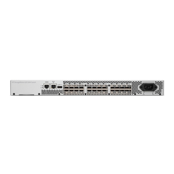
Provides DPS, which optimizes fabric-wide performance and load balancing by automatically routing data to the most efficient available path in the fabric. Provides universal ports that self-configure as E_Ports, F_Ports, M_Ports, or FL_Ports. Port side of the 8/8 and 8/24 SAN Switch The port side of the 8/8 and 8/24 SAN Switch includes the system status LED, console port, Ethernet port, USB port, and FC ports with corresponding port status LEDs. -
Page 10: 8/40 San Switch Features
license appears under the licenseshow command as Full Fabric License and indicates that E_Ports are now enabled automatically. 8/40 SAN Switch features Provides the EZSwitch Setup Wizard for easy setup and basic configuration. Support for 1, 2, 4, and 8 Gb/s autosensing FC switch and router ports. Integrates a single motherboard design with 667 MHz PowerPC 440EPx RISC CPU and integrated peripherals which provide high performance. -
Page 11: Activating Additional 8/40 San Switch Ports
Figure 3 Nonport side view—8/40 SAN Switch 1. Fan (for power supply/fan FRU2) 5. Fan (for power supply/fan FRU1) 2. Power supply/fan status LED (for power supply/fan 6. Power supply/fan status LED (for power supply/fan FRU FRU2) 3. Power supply connector (for power supply/fan FRU2) 7. -
Page 12: Nonport Side Of The 8/80 San Switch And The Encryption San Switch
Figure 4 Port side view—8/80 SAN Switch 1. 8/80 SAN Switch 9. FC ports 16–23 2. Switch ID pull-out tab 10. FC ports 24–31 3. Status LED (top) power LED (bottom) 11. FC ports 32–38 4. Console port 12. FC ports 40–47 5. -
Page 13: Activating Additional 8/80 San Switch Ports
Figure 5 Nonport side view—8/80 SAN Switch 1. 8/80 SAN Switch 5. Fan assembly #2 2. Nonport side 6. Fan assembly #1 3. Power supply #2 7. Power supply #1 4. Fan assembly #3 Activating additional 8/80 SAN Switch ports By default, the 8/80 SAN Switch model integrates 48 licensed ports (ports 0 through 47). -
Page 14: Port Side Of The Encryption San Switch
IR Fabric Service (optional) to enable encryption capabilities across multiple fabrics NPIV support Two hot-swappable, redundant power supply FRUs Three hot-swappable fan FRUs in the N+1 configuration to provide hardware-redundant cooling One RJ-45 10/100/1000 Ethernet management port Two RJ-45 GE ports for clustering interconnection and re-key, and DEK synchronization within cluster One RJ-45 serial console port A USB port that facilitates firmware upgrades, serviceability, and system-log functionality... -
Page 15: Fcoe Converged Network Switch Features
Support for Layer 2 protocols STP/MSTP/RSTP (802.1q) and Link Aggregation (802.1ad) Hewlett Packard Enterprise branded 10-Gb SFP+ (SR and LR) and active copper cables Provides CEE port to CEE port latency of 570 ns (same ASIC) and 1,050 ns (different ASIC) -
Page 16: Port Side Of The Fcoe Converged Network Switch
Port side of the FCoE Converged Network Switch Figure 7 (page 16) shows the port side of the FCoE Converged Network Switch. Figure 7 Port side of the FCoE Converged Network Switch 1. Switch ID pull-out tab 6. 10-GbE ports 0–7 2. -
Page 17: Feature Comparison Of Base And Upgraded Products
Adaptive Rate Limiting ◦ Configurable minimum and maximum committed bandwidth per FCIP tunnel ◦ Minimum rate is guaranteed rate FC Frame Compression before FCIP Encapsulation SOTCP with reorder resistance FastWrite over FCIP (not over FC) Open Systems Tape Pipelining over FCIP FCIP QoS TCP Performance Graphing in Web Tools FICON and FICON Cascading ready. -
Page 18: Available Licenses
Table 1 Comparison of 1606 Extension SAN Switch features (continued) Feature Base product With upgrade license Fibre Channel Routing between remote fabrics for fault isolation FCIP Tunnel Number of FCIP tunnels FCIP Trunking Adaptive Rate Limiting FC Frame Compression SOTCP FastWrite over FCIP Tunnel Open Systems Tape Pipelining over FCIP Tunnel... -
Page 19: Port Side Of The 1606 Extension San Switch
FICON CUP FICON Accelerator For information on these features, see the Fabric OS Administrator’s Guide. Port side of the 1606 Extension SAN Switch Figure 9 (page 19) shows the components on the port side of the 1606 Extension SAN Switch. Figure 9 Port side of the HPE 1606 Extension SAN Switch 1. -
Page 20: Installing And Activating Port Upgrade Licenses
Obtain the WWN from the Switch ID pull-out tab located on the port side of your switch. Alternately, you can use the switchshow command to display the WWN. Contact your Hewlett Packard Enterprise representative to purchase the appropriate Port Upgrade license. Hewlett Packard Enterprise requires the switch WWN obtained in Step 2 to assign a license key. -
Page 21: Supported Sfp Transceiver Options
For example, the Fibre Channel ports on the SAN Switch are numbered from left to right and color-coded into groups of eight to indicate which ports you can combine into trunked groups. Figure 12 (page 21) shows the 8/8 SAN Switch with three trunked groups of eight ports. NOTE: If your 8-Gb SAN Switch is licensed for ISL Trunking (for example, Power Pack+ models ship with this license), use the trunking groups available on the switch. -
Page 22: 8-Gb San Switch Software Options
AW538A 8-Gb SAN Switch software options The following optional software kits and licenses are available. More information on these products is include in the product QuickSpecs, which can be accessed from the Hewlett Packard Enterprise website: http://h18006.www1.hp.com/storage/networking/b_switches/san/index.html HPE StorageWorks Full Fabric Upgrade License... -
Page 23: 8-Gb San Switch Hardware Options
HPE StorageWorks Extension SAN Switch Advanced LTU HPE StorageWorks 1606 Extension SAN Switch FICON Control Unit Port LTU HPE StorageWorks 1606 Extension SAN Switch Integrated Routing LTU (purchase for 1606 Extension SAN Switch only) HPE 1606 Switch FICON CUP Accelerator LTU HPE StorageWorks Power Pack Upgrade HPE B-series 24-40 Port SAN Switch Integrated Routing LTU (purchase for 8/40 SAN Switch only) -
Page 24: Installing And Configuring An 8-Gb San Switch
2 Installing and configuring an 8-Gb SAN Switch This chapter provides information about and instructions to install and configure an 8-Gb SAN Switch. Shipping carton contents Figure 13 (page 24) Table 4 (page 25) identify shipping carton contents for a typical 8-Gb SAN Switch. -
Page 25: Installation And Safety Considerations
Installation and safety considerations You can install the switch in a rack or as a standalone device on a flat surface. Hewlett Packard Enterprise highly recommends mounting the switch in one of the following Hewlett Packard Enterprise customized racks: HPE System/e Rack... -
Page 26: Environmental Considerations
Environmental considerations Before installing the switch, verify that the following environmental requirements are met: Install the switch with the nonport side, which contains the air intake vents, facing the cool-air aisle. All equipment in the rack forces air in the same direction, to avoid taking in exhaust air. A minimum of 24 cubic ft/min of airflow is available to the air intake vents on the nonport side of the switch. -
Page 27: Items Required For Installation
Keep LEDs visible by routing port cables and other cables away from the LEDs. CAUTION: Do not use tie wraps on fiber optic cables because wraps are easily overtightened and can damage the optical fibers. Use Velcro straps to secure and organize fiber optic cables. Items required for installation Obtain the following: 8-Gb SAN Switch installed and connected to a power source... -
Page 28: Supported Devices
HPE 10000 G2 Series Rack HPE System/e Rack NOTE: In this document, “HPE 10000 Series Rack” refers to both the HPE 10000 Series Rack and the HPE 10000 G2 Series Rack. Supported devices Use the SAN Switch Rack Mount Kit to install the following switch models: SAN Switch 2/8V SAN Switch 2/8 SAN Switch 2/8-EL... -
Page 29: Installation And Safety Guidelines
SAN Switch 2/16V 4/8 SAN Switch 4/16 SAN Switch 4/32B SAN Switch 8/8 SAN Switch 8/24 SAN Switch (page 36) for instructions on installing the plenum. Installation and safety guidelines Verify that the rack and the area around the rack meet the following requirements: Plan a rack space that is 1.5 units high (6.7 cm or 2.6 inches), 48.3 cm (19 inches) wide, and at least 68.6 cm (23 inches) deep. -
Page 30: Installing The Hpe San Switch Rack Mount Kit In Your Hewlett Packard Enterprise Custom Rack
Installing the HPE SAN Switch Rack Mount Kit in your Hewlett Packard Enterprise custom rack The SAN Switch Rack Mount Kit enables you to install your Hewlett Packard Enterprise device in the following Hewlett Packard Enterprise custom racks: HPE System/e Rack... - Page 31 Table 5 SAN Switch Rack Mount Kit hardware (continued) Item Description NOTE: All devices require 10 screws except for the 4/32B SAN Switch, MP Router, Encryption SAN Switch, and FCoE Converged Network Switch, which require only 6 screws. Ten #10-32 x 1/2-inch Phillips panhead screws with captive star lock washers Eight #10 alignment washers Eight #10 adapter washers Two 1/4-20 hex nuts with captive star lock washers...
- Page 32 Figure 14 Installing the rear mounting brackets (HPE 10000 Series rack) Figure 15 Installing the rear mounting brackets (HPE System/e rack) NOTE: The SAN Switch Rack Mount Kit contains rails labeled Left and Right to designate the left side and right side of the cabinet as viewed from the front of the cabinet. Installing and configuring an 8-Gb SAN Switch...
- Page 33 Assemble the outer rails: Attach the left outer rail and the right outer rail to the rear mounting brackets using two 1/4-20 hex nuts with captive star lock washers attached loosely, as shown in Figure 16 (page 33). Do not tighten the nuts. Figure 16 Installing the outer rails (HPE 10000 Series rack) Depending on the rack you are using, complete one of the following tasks: For an HPE 10000 Series Rack, install two #10-32 x 1/2-inch Phillips panhead...
- Page 34 Table 6 (page 34) to determine the screw type and the number of screws required for your device. CAUTION: Use only the screws provided in the SAN Switch Rack Mount Kit. Using other screws can cause damage to internal components. Table 6 Screws required to assemble the inner rails Device #8-32 x 5/16-inch screws...
- Page 35 To attach the inner rails to the 4/8, 4/16, 8/8, or 8/24 SAN Switch, use the five screw holes marked 8. The plenum requires one screw hole marked 8 and one screw hole marked 16, as shown in (page 36). To attach the inner rails to the 4/32, 4/32B, 4/64, 8/40, or 8/80 SAN Switch, or the 400 MP Router, use the screw holes marked 16, as shown in Figure 20 (page...
-
Page 36: Installing The Plenum (If Required)
If you are installing one of the following devices, install the plenum included in the switch accessory kit: SAN Switch 2/8V SAN Switch 2/16 SAN Switch 2/16V 4/8 SAN Switch 4/16 SAN Switch 4/32B SAN Switch 8/8 SAN Switch 8/24 SAN Switch (page 36) for complete installation instructions. -
Page 37: Securing The Device To The Outer Rails
Securing the device to the outer rails To secure the device to the outer rails: Insert the switch with the attached inner rails into the outer rails. NOTE: This step applies to the installation of a device in an HPE 9000 Series Rack or HPE System/e Rack. -
Page 38: Connecting The San Switch To The Fabric
Connecting the SAN Switch to the fabric This section describes the procedure for connecting the SAN Switch to the fabric. EZSwitch Setup (optional) After you have set up the 8-Gb SAN Switch in a rack or as a standalone switch, you can power it on and configure it. -
Page 39: Powering Off The 8-Gb San Switch
Powering off the 8-Gb SAN Switch Execute the sysshutdown command. This command shuts down the key processors and powers off the switch. All LEDs extinguish. Set each AC power switch to O. Making a serial connection All basic configuration tasks require a serial connection. Connect the serial cable to an RS-232 serial port on the workstation, as shown in Figure 24 (page 39). -
Page 40: Dhcp
DHCP When using DHCP, the 8-Gb SAN Switch obtains an IP address, subnet mask, and default gateway address from the DHCP server. The DHCP client can only connect to a DHCP server that is on the same subnet as the switch. If your DHCP server is not on the same subnet as the 8-Gb SAN Switch, use a static IP address. -
Page 41: Setting The Switch Date And Time
Modify the domain ID, if required. The default domain ID is 1. If the switch is not powered on until after it is connected to the fabric and the default domain ID is already in use, the domain ID for the new switch is automatically reset to a unique value. -
Page 42: Setting The Time Zone
If the time zone is not set with the new options, the switch retains the offset time zone settings. The tstimezone command includes an option to revert to the prior time zone format. For more information about the --old option, see the Fabric OS Command Reference Manual. You can use the tstimezone command to: Display all of the time zones supported in the firmware. -
Page 43: Correcting The Time Zone
You can synchronize the local time of the principal or primary FCS switch to a maximum of eight external NTP servers. To keep the time in your SAN current, Hewlett Packard Enterprise recommends that the principal or primary FCS switch has its time synchronized with at least one external NTP server. - Page 44 For more information on using an NTP server, and IPv6 considerations, see the Fabric OS Administrator's Guide. Installing and configuring an 8-Gb SAN Switch...
-
Page 45: Verifying The Configuration
Issue the fabricshow command from the workstation. This command provides general information about the fabric. Backing up the configuration Hewlett Packard Enterprise recommends regular backups to ensure that a recent configuration is available. To back up the switch configuration to an FTP server: Issue the configupload command. -
Page 46: Changing The Switch Name And Chassis Name
Changing the switch name and chassis name Changing the switch and chassis names is important for accurate tracking of errors in the RASlog. The messages in the log are labeled with the switch or chassis name, so choose a meaningful name for the switch and chassis. -
Page 47: Managing The 8-Gb San Switches
3 Managing the 8-Gb SAN Switches The 8-Gb SAN Switches are designed for high availability and low failure. They do not require any regular physical maintenance. They include diagnostic tests and field-replaceable units for the HPE StorageWorks 8/40 and 8/80 SAN Switches, the Encryption SAN Switch the FCoE Converged Network Switch, and the 1606 Extension SAN Switch. -
Page 48: Configuring The Fcoe Converged Network Switch
Configuring the FCoE Converged Network Switch For more information on configuring the CEE portion of the FCoE Converged Network Switch, see the Brocade Converged Enhanced Ethernet Administrator's Guide. Configuring the 1606 Extension SAN Switch The following sections provide information on configuring the 1606 Extension SAN Switch. FCIP and Fibre Channel routing services configuration Initially, the FC ports on the 1606 Extension SAN Switch are set to persistently disabled. -
Page 49: Verifying Switch Operation
Verifying switch operation To verify correct operation of the 1606 Extension SAN Switch: Check the LEDs to verify that all components are functional (see (page 60)). Execute the portcfgpersistentenable command to activate the FC ports for FC operation. Verify correct operation of the switch by entering the switchshow command from the workstation. -
Page 50: 8-Gb San Switch Leds
8-Gb SAN Switch LEDs System activity and status can be determined through the activity of the LEDs on the switch. The LED states are as follows: No light Steady light Flashing light The LEDs are either green or amber. 8/8 and 8/24 SAN Switch LEDs 8/8 and 8/24 SAN Switch LEDs are located on the port side only. -
Page 51: 8/40 San Switch Leds
8/40 SAN Switch LEDs 8/40 SAN Switch LEDs are located on the port side and nonport side. See Figure 27 (page 51) Figure 28 (page 51). Figure 27 Identifying 8/40 SAN Switch port side LEDs 1. System status LED (top) and system power (bottom) 2. -
Page 52: 8/80 San Switch Leds
8/80 SAN Switch LEDs 8/80 SAN Switch LEDs are located on the port side and nonport side. See Figure 29 (page 52) Figure 30 (page 53). Figure 29 Identifying 8/80 SAN Switch port side LEDs 1. 8/80 SAN Switch 8. FC ports (0 through 7) 2. -
Page 53: Port Side Led Activity For The 8/80 San Switch
Figure 30 Identifying 8/80 SAN Switch nonport side LEDs 1. Power supply #2 status LED 6. Power supply #1 status LED 2. Power supply #2 7. Power supply #1 3. Fan assembly #3 8. Fan assembly #1 status LED 4. Fan assembly #2 9. -
Page 54: Nonport Side Led Activity For The 8/80 San Switch
Table 8 8-Gb SAN Switch port side LED patterns (continued) LED name LED color Status of hardware Recommended action Ethernet speed No light Port speed is 10 Mb/sec. No action required. Steady green Port speed is 100 Mb/sec. No action required. Ethernet link No light There is no link. -
Page 55: Port Side Led Activity For The Encryption San Switch
Table 9 Nonport side LED patterns during normal operation (continued) LED name LED color Status of hardware Recommended action NOTE: When the switch is first powered on the power supply status LED will show amber until POST has completed. Fan status No light Fan assembly is not receiving Do the following:... - Page 56 Table 10 Encryption SAN Switch and FRU LEDs (continued) LED name LED color Status of hardware Recommended action Ethernet link No light There is no link. Verify that the Ethernet cable is connected properly. Steady green There is a link. No action required.
-
Page 57: Port Side Led Activity For The Fcoe Converged Network Switch
Table 10 Encryption SAN Switch and FRU LEDs (continued) LED name LED color Status of hardware Recommended action Check the power cable The power cable is connection. disconnected. Replace the power supply FRU. The power supply FRU has failed. NOTE: When the switch is first powered on, the power supply status LED shows amber until... - Page 58 Table 11 FCoE Converged Network Switch port side LED patterns LED name LED color Status of hardware Recommended action Power status No light System is off or there is an internal Verify the following: power supply failure. System is powered on (power supply switches to 1).
-
Page 59: Nonport Side Led Activity For The Fcoe Converged Network Switch
Table 11 FCoE Converged Network Switch port side LED patterns (continued) LED name LED color Status of hardware Recommended action Steady green Online No action required. Slow blinking green (2 Online but segmented (loopback No action required. seconds) cable or incompatible switch) Fast blinking green Internal loopback (diagnostic) No action required. -
Page 60: Port Side Led Activity For The 1606 Extension San Switch
Table 12 (page 60) describes the LEDs on the nonport side of the switch. Table 12 FCoE Converged Network Switch nonport side LED patterns LED name LED color Status of hardware Recommended action Power supply No light Power supply is not receiving Verify the power supply is on and status power or is off. - Page 61 Figure 33 Port side LEDs on the 1606 Extension SAN Switch 1. System status LED 9. Port 0 status LED 2. System power LED 10. Port 4 status LED 3. Console port 11. Port 8 status LED 4. Ethernet link LED 12.
- Page 62 Table 13 1606 Extension SAN Switch port side LED patterns (continued) System status No light System is off or there is no power. Verify that the system is on and has completed booting. Steady green System is on and functioning No action required.
-
Page 63: Nonport Side Led Activity For The 1606 Extension San Switch
Table 13 1606 Extension SAN Switch port side LED patterns (continued) GbE Optical Port No light Port is offline. Verify that the power LED is on and Status check the SFP and cable. Steady green Port is online but has no traffic. No action required. -
Page 64: Maintaining The 8-Gb San Switches
Verify that the LEDs on the switch indicate that all components are healthy. (LED patterns are described in (page 53) (page 54).) If one or more LEDs do not display a healthy state, do the following: Verify that the LEDs are not set to beacon (this can be determined through the switchshow command or Web Tools). -
Page 65: Diagnostic Tests
Figure 34 Installing an SFP in the upper row of port slot Diagnostic Tests In addition to POST, Fabric OS includes diagnostic tests to help you troubleshoot the hardware and firmware. This includes tests of internal connections and circuitry, fixed media, and the transceivers and cables in use. -
Page 66: Fan Assembly
of failure. Check the management interface and the error log for details on the cause of status. In Web Tools, check the Fan Status icon background color. It will be either yellow or red if the fan has failed. When the fan is functioning correctly, the background color is green. Enter the fanshow command at the command prompt to display fan status: switch:admin>... -
Page 67: Replacing The 8/40 San Switch Power Supply And Fan Assembly
Table 15 Fan status LED behavior, description, and required actions LED color and behavior Description Action required No light Fan assembly is not receiving power. Verify that the fan FRU is seated correctly. Steady green Fan assembly is operating normally. No action required. -
Page 68: Replacing The 8/80 San Switch And Encryption San Switch Fan Assembly
Figure 36 8/80 and Encryption SAN Switch fan assemblies on the nonport side 1. 8/80 SAN Switch 4. Fan assembly #2 2. Nonport side 5. Fan assembly #3 3. Fan assembly #1 CAUTION: Disassembling any part of the fan assembly voids the part warranty and regulatory certifications. -
Page 69: Replacing An 8/80 San Switch Or Encryption San Switch Power Supply
Install the new fan assembly in the chassis: Orient the new fan assembly as shown in Figure 37 (page 69), with the captive screw on the right. Gently push the fan assembly into the chassis until it is firmly seated. CAUTION: Do not force the installation. - Page 70 Replacing a power supply takes approximately two minutes. You will need: 8/80 SAN Switch or Encryption SAN Switch New power supply Phillips-head screwdriver #1 To replace a power supply: If the switch remains powered on, verify that the functioning power supply (the one not being replaced) has been powered on for at least four seconds and displays a green LED.
-
Page 71: Power Supply
Gently push the power supply into the chassis until it is firmly seated. CAUTION: Do not force the installation. If the power supply does not slide in easily, make sure that it is correctly oriented before continuing. Secure the power supply to the chassis by tightening the captive screw. Plug the power cord into the power supply and then press the AC power switch to turn it on. - Page 72 Table 16 Management tools Management tool Out-of-band support In-band support CLI—Up to two admin sessions and four user Ethernet or serial connection IP over FC sessions simultaneously Web Tools—For information, see the Web Tools Ethernet or serial connection IP over FC Administrator's Guide for the Fabric OS version running on your switch.
-
Page 73: Technical Specifications
4 Technical specifications Weight and physical dimensions Table 17 (page 73) lists the physical dimensions for the SAN Switches. Table 17 8-Gb SAN Switch physical dimensions Property 8/8 and 8/24 8/40 SAN 8/80 SAN Switch Encryption FCoE 1606 Extension SAN Switches Switch SAN Switch SAN Switch... -
Page 74: Facility Requirements
Table 18 8/8, 8/24 and 8/40 SAN Switch memory Memory type Install memory Main Memory (SDRAM) 512 MB Boot Flash 8/40 SAN Switch only: 4 MB Compact Flash 1 GB Table 19 (page 74) lists the 8/80 SAN Switch, Encryption SAN Switch, and FCoE Converged Network Switch memory specifications. -
Page 75: Electromagnetic Compatibility
Table 21 Facility requirements (continued) Type Requirements FCoE Converged Network Switch—Air flows from the nonport side to the port side. Maximum airflow of 71.36 cu m/h (42 cu ft/min), nominal airflow of 59.47 cu m/h (35 cu ft/min). Cabinet (when 8/8, 8/24, and 8/40 SAN Switches, FCoE Converged Network Switch, and 1606 Extension rack mounted) SAN Switch—One rack unit in a 48.3 cm (19 inch) cabinet. -
Page 76: Data Transmission Ranges
Table 23 Power supply specifications (continued) Specification Description System power consumption 8/8 and 8/24 SAN Switches: 48 W nominal, 57 W maximum 8/40 SAN Switch: 84 W nominal, 91 W maximum 8/80 SAN Switch: 260 W nominal, 300 W maximum Encryption SAN Switch: 100–240 VAC, universal FCoE Converged Network Switch: 182.4 W nominal, 306 W maximum 1606 Extension SAN Switch: 95 W nominal, 116 W maximum... - Page 77 Table 24 Laser data transmission ranges for the 8/8 and 8/24 SAN Switches (continued) Port speed Cable size Short wavelength Long wavelength (microns) 8 Gb/s 150 m 62.5 21 m 10 km Table 25 Laser data transmission ranges for the 8/40 SAN Switch Port speed Cable size Short wavelength...
- Page 78 Table 26 Laser data transmission ranges for the 8/80 SAN Switch (continued) Port speed Cable size Short wavelength Long wavelength Extended long wavelength (microns) 50 to 100 km with an HPE Extended Fabrics license 4 Gb/s 150 m (492 ft) 62.5 70 m (230 ft) 10 km...
-
Page 79: Fcoe Converged Network Switch Data Flow Latency
Table 28 Laser data transmission ranges for the 1606 Extension SAN Switch Fibre Channel ports Port speed Cable size Short wavelength Long wavelength Extended long wavelength (microns) 1 Gb/s 500 m (1,640 ft) (OM2) 860 m (2,821 ft) (OM3) 62.5 300 m (984 ft) 10 km (6.2 miles) 80 km (50 miles) -
Page 80: Post And Boot Specifications
The ports are capable of operating at 1, 2, 4, or 8 Gb/s and are able to autonegotiate to the maximum link speed. POST and boot specifications The switch performs POST by default each time it is powered on or rebooted or the system is reset. -
Page 81: Support And Other Resources
Operating system type and revision level Detailed questions Subscription service Hewlett Packard Enterprise recommends that you register your product at the Subscriber's Choice for Business website: http://www.hp.com/go/wwalerts After registering, you will receive email notification of product enhancements, new driver versions, firmware updates, and other product resources. -
Page 82: Hp Websites
HP websites For additional information, see the following HP websites: http://www.hp.com http://www.hp.com/go/storage http://www.hp.com/service_locator http://www.hp.com/support/manuals http://www.hp.com/support/downloads Rack stability Rack stability protects personnel and equipment. WARNING! To reduce the risk of personal injury or damage to equipment: Extend leveling jacks to the floor. Ensure that the full weight of the rack rests on the leveling jacks. -
Page 83: Typographic Conventions
HPE CSR programs allow you to repair your StorageWorks product. If a CSR part needs replacing, Hewlett Packard Enterprise ships the part directly to you so that you can install it at your convenience. Some parts do not qualify for CSR. Your Hewlett Packard Enterprise-authorized service provider will determine whether a repair can be accomplished by CSR. -
Page 84: A Regulatory Compliance And Safety
Laser device All Hewlett Packard Enterprise systems equipped with a laser device comply with safety standards, including IEC 825. With specific regard to the laser, the equipment complies with laser product performance standards set by government agencies as a Class 1 laser product. The product does not emit hazardous light. -
Page 85: Laser Product Label
Figure 39 (page 85) or equivalent may be located on the surface of the Hewlett Packard Enterprise supplied laser device. Figure 39 Class 1 laser product label This optional label indicates that the product is classified as a CLASS 1 LASER PRODUCT. This label may appear on the laser device installed in your product. -
Page 86: Japanese Notice
Do not disassemble, crush, puncture, short external contacts, or dispose of in fire or water. Replace only with the Hewlett Packard Enterprise spare part designated for this product. Batteries, battery packs, and accumulators should not be disposed of together with the general household waste. -
Page 87: Taiwan Battery Recycling Notice
Taiwan battery recycling notice The Taiwan EPA requires dry battery manufacturing or importing firms in accordance with Article 15 of the Waste Disposal Act to indicate the recovery marks on the batteries used in sales, giveaway, or promotion. Contact a qualified Taiwanese recycler for proper battery disposal. Power cords The power cord set must meet the requirements for use in the country where the product was purchased. -
Page 88: Czechoslovakian Notice
van uw afgedankte apparatuur bij een inzamelingspunt voor het recyclen van oude elektrische en elektronische apparatuur. Door uw oude apparatuur apart aan te bieden en te recyclen, kunnen natuurlijke bronnen worden behouden en kan het materiaal worden hergebruikt op een manier waarmee de volksgezondheid en het milieu worden beschermd. -
Page 89: German Notice
des appareils mis au rebut, veuillez contacter les autorités locales de votre région, les services de collecte des ordures ménagères ou le magasin dans lequel vous avez acheté ce produit. German notice Entsorgung von Altgeräten aus privaten Haushalten in der EU Das Symbol auf dem Produkt oder seiner Verpackung weist darauf hin, dass das Produkt nicht über den normalen Hausmüll entsorgt werden darf. -
Page 90: Latvian Notice
ulteriori informazioni relative ai punti di raccolta delle apparecchiature, contattare l'ente locale per lo smaltimento dei rifiuti, oppure il negozio presso il quale è stato acquistato il prodotto. Latvian notice Lithuanian notice Polish notice Portuguese notice Descarte de Lixo Elétrico N/A Comunidade Européia Este símbolo encontrado no produto ou N/A embalagem indica que o produto não deve ser descartado no lixo doméstico comum. -
Page 91: Slovakian Notice
da HP em sua cidade, com o serviço de coleta de lixo ou com a loja em que o produto foi adquirido. Slovakian notice Slovenian notice Spanish notice Eliminación de residuos de equipos eléctricos y electrónicos por parte de usuarios particulares en la Unión Europea Este símbolo en el producto o en su envase indica que no debe eliminarse junto con los desperdicios generales de la casa. - Page 92 affären där du köpte produkten för att få mer information om var du kan lämna ditt avfall för återvinning. Regulatory compliance and safety...
-
Page 93: B Electrostatic Discharge
B Electrostatic discharge This appendix provides the following information: How to prevent electrostatic discharge (page 93) Grounding methods (page 93) How to prevent electrostatic discharge To prevent damage to the system, you must follow certain precautions when setting up the system or handling parts. -
Page 94: Glossary
Advanced Performance Monitor ASIC Application-Specific Integrated Circuit. B-series Fibre Channel switches and FICON directors manufactured for Hewlett Packard Enterprise by Brocade Communications Systems, Inc. C-series Fibre Channel switches and FICON directors manufactured for Hewlett Packard Enterprise by Cisco Systems, Inc. - Page 95 Electromagnetic compatibility. Electromagnetic Interference. enterprise Any large organization where information technology is essential for continuing operations. Enterprise A storage system based on an HSG60 or HSG80 controller. These systems include MA6000, Modular Array MA8000, RA8000, EMA12000, EMA16000, and ESA12000 storage systems. ESCON Enterprise Systems Connection.
- Page 96 1. Long-wave laser. 2. Long wavelength. M-series Fibre Channel switches manufactured for Hewlett Packard Enterprise by McDATA Corporation. Metropolitan area network. A communications network that covers a geographic area such as a town, city, or suburb. Management Information Base (B-series).
- Page 97 Service pack. A collection of software updates. SPOCK Single Point of Connectivity Knowledge. An Hewlett Packard Enterprise website as the primary portal to obtain detailed information about supported HPE StorageWorks product configurations (http://www.hp.com/storage/spock). An HP Passport account is required for access.
- Page 98 Universal Serial Bus. Universal Time Conversion. The default time zone for switches, 8 hours ahead of Pacific Standard Time. VE_Port Virtual Fibre Channel E_Port. Virtual private network. VSAN Virtual storage area network. A logical SAN partition that can be configured and managed independently.
-
Page 99: Index
Index Symbols 1606 Extension SAN switch cabling and configuring, 37 configuring, 48 cabling considerations, 26 features, 16 changing switch name, 46 FRUs, 65 commands LED activity, 60 configupload, 45 verifying operation, 49 fabricshow, 45 8-Gb SAN switches ipaddrshow, 40 hardware options, 23 licenseadd, 20 installing and configuring, 24 licenseshow, 20... - Page 100 86 HBAs, supported, 80 Japanese power cord, 87 help Taiwan battery recycling, 87 obtaining, 81 Hewlett Packard Enterprise technical support, 81 optional hardware kits, 23 HPE StorageWorks SAN switches 1606 Extension SAN Switch, 8 8/24, 7 physical specifications, 73...
- Page 101 82 specifications, 75 websites psshow command, 71 customer self repair, 83 Hewlett Packard Enterprise Subscriber's Choice for Business, 81 rack mount considerations, 26 HP , 82 rack stability product manuals, 81 warning, 82 weight specifications, 73...
Need help?
Do you have a question about the StorageWorks 8/8 Base SAN Switch and is the answer not in the manual?
Questions and answers