Table of Contents
Advertisement
Quick Links
Advertisement
Table of Contents

Subscribe to Our Youtube Channel
Related Manuals for Shindaiwa C254


Summary of Contents for Shindaiwa C254
- Page 1 X7502825601 06/10 SHINDAIWA OWNER’S/OPERATOR’S MANUAL C254 BRUSHCUTTER WARNING! Minimize the risk of injury to yourself and oth- ers! Read this manual and familiarize yourself with the contents. Always wear eye and hearing protection when operating this unit.
-
Page 2: Table Of Contents
If you have questions regarding your H4 series hand-held power equipment, or if you do not understand something in this manual, contact Shindaiwa at the address printed on the back of this Manual. -
Page 3: Safety
Safety and Operation Information Labels: Make sure all information labels are undamaged and readable. Immediately replace damaged or missing information labels. New labels are available from your local autho- rized Shindaiwa dealer. WARNING! Never oper- ate power equipment of any kind if you are tired or if you... - Page 4 Safety (continued) The Properly Equipped Operator Wear hearing protection devices and a broad-brimmed hat or helmet. A helmet is required when using a blade-equipped brushcutter to clear small trees. Prolonged exposure to excessive noise is fatiguing and could lead to impaired hearing.
-
Page 5: Product Description
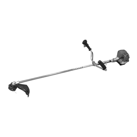
Strap WARNING! Do not make unauthorized modifications or alterations to any of these units or their components. C254 4-cycle, vertical cylinder, air cooled 6.1 kg/14.1 lb. 34 x 27 mm / 1.3 x 1.1 in. 24.5 cc/1.5 cu. in. 590 ml/20.0 oz. -
Page 6: Emission Control
Emission Control (Exhaust & Evaporative) EPA 2010 and Later and/or C.A.R.B. TIER III The emission control system for the engine is EM/TWC (Engine Modification and 3-way Catalyst) and for the fuel tank the Control System is EVAP (Evaporative Emissions) or N (for nylon tank). Evaporative emission may be applicable to California models only. -
Page 7: To Advance Trimmer Line
Cutting attachment shield Tools Required: Screwdriver Parts Required: Plastic debris shield, shield plate, (3) 5 x 10 mm screws CAUTION Wear Gloves or personal injury may result: • Cutoff knife is sharp. • Gearcase and surrounding area may be hot. The plastic shield is for use with the Nylon Line Head only. -
Page 8: Throttle Linkage And Ignition Leads
Assembly (continued) Throttle Linkage and Ignition Leads Adjust throttle trigger free play The throttle trigger free play should be approximately 4 - 6 mm (3/16” - 1/4”). Make sure that the throttle lever operates smoothly without binding. Loosen the air cleaner cover knob(s) and remove the air cleaner cover. - Page 9 d. Remove three screws holding shield plate (E) and plastic shield (C) to gear housing. e. Retain line head (B), adapter plate (D), shield plate, and plastic shield for conversion back to nylon line head operation. Loosely attach bracket (I) to shield (J) and attach shield to bottom of gear housing (F) with hardware provided.
-
Page 10: Mixing Fuel
Mixing Fuel WARNING! Alternative fuels, such as E15 (15% ethanol), E-85 (85% ethanol) or any fuels not meeting Shindaiwa requirements are NOT approved for use in Shindaiwa gasoline engines. Use of alternative fuels may cause performance problems, loss of power, overheating, fuel vapor lock, and unintended machine operation, including, but not limited to, improper clutch engagement. -
Page 11: Filling The Fuel Tank
Mixing Instructions 1. Fill an approved fuel container with half of the re- quired amount of gasoline. 2. Add the proper amount of engine oil to gasoline. 3. Close container and shake to mix oil with gasoline. 4. Add remaining gasoline, close fuel container, and remix. -
Page 12: Starting The Engine
Starting the Engine Engine ignition is controlled by a two position switch mounted on the throttle housing labeled, “I” for ON or START and “O” for OFF or STOP. WARNING! The attachment will operate immediately when the engine starts and could result in loss of control and possible Starting the Engine serious injury. -
Page 13: Stopping The Engine
NEVER allow the engine to run at high the unit to your Shindaiwa dealer for RPM without a load. Doing so could inspection. damage the engine. - Page 14 Cutting grass with a trimmer head Your Shindaiwa unit may be equipped with one of several Shindaiwa trimmer head models, each with features for specific applications and/or operational requirements. NOTE: For proper operation, always refer to the instructions accompanying the trim- mer head being used.
-
Page 15: Using A Blade
When cutting wood with a blade, feed the blade slowly—never strike or “slam” a spinning blade against the wood. WARNING! DO NOT use 2-tooth or non-Shindaiwa approved 4-tooth cutting blades with Shindaiwa trimmers and brushcutters. ■ Never use a blade for purposes other than those for which it was designed. -
Page 16: Maintenance
Air Filter The H4 engine that powers your Shindaiwa model is a hybrid 4-stroke engine. As a hybrid, the engine is lubri- cated by oil mixed with the gasoline and air from the carburetor that moves... - Page 17 Maintenance (continued) 10-Hour maintenance (more frequently in dusty conditions) Remove the air filter cover by loos- ening the cover screw(s) and lifting. Remove and inspect the pre-filter. If the pre-filter is torn or otherwise damaged, replace it with a new one.
- Page 18 ■ Combustion chamber should be decarbonized, and the valve clearance should be adjusted. It is highly recommended that this is done by a Shindaiwa-trained service technician. ■ Replace the spark plug annually: Use only the type recommended in the ”Specifications” section or an equivalent resis- tor type spark plug of the correct heat range.
-
Page 19: Carburetor Adjustment
This engine has been factory adjusted to maintain satisfactory starting, emission, and durability performance up to 1,100 feet above sea level (ASL) (96.0 kPa). To maintain proper engine operation and emission compliance above 1,100 feet ASL the carburetor may need to be adjusted by an authorized Shindaiwa service dealer. IMPORTANT! -
Page 20: Blade Sharpening
WARNING! The cutting attachment must NEVER rotate at engine idle! If the idle speed cannot be adjusted by the procedure described here, return the unit to your Shindaiwa dealer for inspection. Blade Sharpening WARNING! Wear protective gloves when handling or performing main- tenance on the blade. -
Page 21: Long Term Storage
Loading Trimmer Line Cut one piece of line to recommended length. Align arrows on top of knob with openings in eyelets. Insert one end of trimmer line into an eyelet, and push line equal distance through trimmer head. Hold trimmer head while turning knob clockwise to wind line onto spool until about 5”... -
Page 22: Troubleshooting Guide
Consult with an authorized Shindaiwa servicing dealer. Adjust valves. Valve clearance too loose. ENGINE DOES NOT START Possible Cause Consult with an authorized Shindaiwa servicing dealer. Faulty recoil starter. Fluid in the crankcase. Internal damage. Tighten and re-test. Loose spark plug. - Page 23 89 or higher mixed with an air cooled engine oil that meets or exceeds ISO-L-EGD and/or JASO FD classifi ed oils at 50:1 gasoline/oil ratio. Consult with an authorized Shindaiwa servicing dealer. Consult with an authorized Shindaiwa servicing dealer.
- Page 24 Consult with an authorized Shindaiwa servicing dealer. Adjust idle. Check Specifi cations page for correct idle speed. Consult with an authorized Shindaiwa servicing dealer. Adjust idle. Check Specifi cations page for correct idle speed. Replace spring/shoes as required, check idle speed.
-
Page 25: Warranty
The owner shall demonstrate reasonable care and use, and follow preventative maintenance, storage, fuel and oil usage as pre- scribed in the operator’s manual. Should a product difficulty occur, you must, at your expense, deliver or ship your Shindaiwa unit to an authorized Shindaiwa servicing dealer for warranty repairs (within the applicable warranty period), and arrange for pick-up or return of your unit after the repairs have been made. - Page 26 89 octane or higher. Gasohol which contains a maximum 10% ethanol (grain alcohol) or 15% MTBE (methyl/tertiary/butyl/ether) is also approved. The prescribed mixing ratio of gasoline to oil is listed on the Shindaiwa oil label and covered in your operator’s manual.
- Page 27 Authorized Dealer within 100 miles, ECHO Inc. will pay to ship the unit to the nearest authorized dealer. If you have questions regarding your warranty coverage, you should contact ECHO Inc. at 1-800-673-1558, web site WWW.ECHO-USA.COM or contact Shindaiwa at 1-877-986- 7783, web site WWW.SHINDAIWA.COM.
- Page 28 NOTES...
- Page 29 NOTES...
- Page 30 NOTES...
- Page 31 NOTES...
-
Page 32: Servicing Information
Genuine Shindaiwa Parts and Assemblies for your Shindaiwa products are available only from an Authorized Shindaiwa Dealer. When you do need to buy parts always have the Model Number, Type and Serial Number of the unit with you. You can find these numbers on the engine. For future reference, write them in the space provided below.
Need help?
Do you have a question about the C254 and is the answer not in the manual?
Questions and answers