Table of Contents
Advertisement
Quick Links
© Copyright 2015
EVERTZ MICROSYSTEMS LTD.
5292 John Lucas Drive,
Burlington, Ontario,
Canada L7L 5Z9
Phone:
+1 905-335-3700
Sales:
sales@evertz.com
Tech Support: service@evertz.com
Web Page:
http://www.evertz.com
Version 0.1, January 2015
The material contained in this manual consists of information that is the property of Evertz Microsystems and is
intended solely for the use of purchasers of the 3400 Series Products. Evertz Microsystems expressly prohibits
the use of this manual for any purpose other than the operation of the 3400 Series product line. Due to on going
research and development, features and specifications in this manual are subject to change without notice.
All rights reserved. No part of this publication may be reproduced without the express written permission of Evertz
Microsystems Ltd. Copies of this manual can be ordered from your Evertz dealer or from Evertz Microsystems.
3400 Series
Coarse WDM Optical Modules
User Manual
Fax: +1 905-335-3573
Fax: +1 905-335-7571
Advertisement
Table of Contents

Related Manuals for evertz 3400 Series


Summary of Contents for evertz 3400 Series
- Page 1 3400 Series Products. Evertz Microsystems expressly prohibits the use of this manual for any purpose other than the operation of the 3400 Series product line. Due to on going research and development, features and specifications in this manual are subject to change without notice.
- Page 2 This page left intentionally blank...
- Page 3 IMPORTANT SAFETY INSTRUCTIONS The lightning flash with arrowhead symbol within an equilateral triangle is intended to alert the user to the presence of uninsulated “Dangerous voltage” within the product’s enclosure that may be of sufficient magnitude to constitute a risk of electric shock to persons. The exclamation point within an equilateral triangle is intended to alert the user to the presence of important operating and maintenance (Servicing) instructions in the literature accompanying the product.
- Page 4 FIBER OPTIC DEVICES Some modules in this product may have fiber optic outputs. The following safety information applies to the optical outputs of these modules. Consult individual chapters for specific safety information for handling fiber optics. WARNING Never look directly into an optical fiber. Irreversible eye damage can occur in a matter of milliseconds.
- Page 5 INFORMATION TO USERS IN EUROPE NOTE CISPR 22 CLASS A DIGITAL DEVICE OR PERIPHERAL This equipment has been tested and found to comply with the limits for a Class A digital device, pursuant to the European Union EMC directive. These limits are designed to provide reasonable protection against harmful interference when the equipment is operated in a commercial environment.
- Page 6 WARNING Changes or Modifications not expressly approved by Evertz Microsystems Ltd. could void the user’s authority to operate the equipment. Use of unshielded plugs or cables may cause radiation interference. Properly shielded interface cables...
-
Page 7: Table Of Contents
1.2.3. 3400DS-8 DISTRIBUTION SPLITTER ............... 8 1.2.4. 3400MS2-4 QUAD MONITORING SPLITTER ............9 1.2.5. 3405MS4-2 DUAL MONITORING SPLITTER ............10 MOUNTING THE 3400 SERIES FRAME ..................11 2.1. MOUNTING THE 3400FR ....................11 2.2. MOUNTING THE STANDALONE FORM FACTOR ............12 INSTALLATION OF 3400 SERIES MODULES ................ - Page 8 Figure 2-1- Fiber Optics Cable Place Holders ....................11 Figure 3-2: Mounting the 3400 Standalone Form Factor ................12 Figure 2-1: 3400 Series Passive Optical Modules ..................13 Figure 3-3: 3400CWDM Typical Connection ....................14 Figure 3-1: 3400CWDM Rear Panel Options ....................14 Page - ii Revision 0.1...
- Page 9 Evertz products are for informational use only and are not warranties of future performance, either expressed or implied. The only warranty offered by Evertz in relation to this product is the Evertz standard limited warranty, stated in the sales contract or order confirmation form.
- Page 10 3400 Series Coarse WDM Optical Modules This page left intentionally blank Page - iv Revision 0.1...
-
Page 11: Overview
Coarse WDM Optical Modules OVERVIEW The Evertz 3400 Series encompasses the 3400FR. The 3400FR is a passive optical frame which is a powerful solution for today’s dense, modular, passive fiber optic distribution needs. The 3400FR provides flexible optical signal distribution in the form of splitter/combiner modules that fit in the passive optical FR frame. - Page 12 3400 Series Coarse WDM Optical Modules There are currently many modules in the passive optical module family. MODEL DESCRIPTION FUNCTION 3400DS2-4 Distribution Splitter/Combiner Quad 1 X 2 optical splitter 3400DS4-2 Distribution Splitter/Combiner Dual 1 X 4 optical splitter 3400DS8 Distribution Splitter/Combiner...
-
Page 13: 3400Cwdm Coarse Wavelength Division Multiplexors
3400 Series Coarse WDM Optical Modules 1.1. 3400CWDM COARSE WAVELENGTH DIVISION MULTIPLEXORS The 3400CWDM’s are bi-directional Multiplexors/De-multiplexors that combine/separate up to sixteen different wavelengths over a single fiber. The 3400CWDM-M4/D4 and 3400CWDM-M8/D8 are designed to mux/demux up to 16 wavelengths in the 1270nm to 1610nm spectrum. While the 3400CWDM-M8LB/D8LB are expandable from four or eight to 12 or 16 channel systems. -
Page 14: Figure 1-2: 3400Cwdm-4 Block Diagram
3400 Series Coarse WDM Optical Modules 3400CWDM-M4 1510nm 1530nm Combined 1510 to 1570nm 1550nm 1570nm Figure 1-2: 3400CWDM-4 Block Diagram 3400CWDM-M8 1470nm 1490nm 1510nm 1530nm Combined 1470 to 1610nm 1550nm 1570nm 1590nm 1610nm Figure 1-3: 3400CWDM-8 Block Diagram Page - 4... -
Page 15: 3400Ds And 3400Ms Splitters
3400 Series Coarse WDM Optical Modules 3400CWDM-M8LB 1270nm 1290nm 1310nm 1330nm Combined 1470 to 1610nm 1350nm 1370nm 1430nm 1450nm Expansion Port Figure 1-4: 3400CWDM-8LB Block Diagram 1.2. 3400DS AND 3400MS SPLITTERS The 3400DS and 3400MS are optical splitters that take a single fiber input and split it proportionately into separate fiber outputs. -
Page 16: 3400Ds2-4 Quad Distribution Splitter
3400 Series Coarse WDM Optical Modules Figure 1-5: 3400DS and 3400MS Splitter/Combiners Functional Block Diagrams 1.2.1. 3400DS2-4 QUAD DISTRIBUTION SPLITTER The 3400DS is used in optical signal distribution applications and splits the signal so that each output fiber carries equal proportions of the input optical power. The 3400DS2-4 is a quad 50/50 passive optical splitter. -
Page 17: 3400Ds4-2 Dual Distribution Splitter
3400 Series Coarse WDM Optical Modules 1.2.2. 3400DS4-2 DUAL DISTRIBUTION SPLITTER The 3400DS is used in optical signal distribution applications and splits the signal so that each output fiber carries equal proportions of the input optical power. The 3400DS4-2 is a dual 25% passive optical splitter. -
Page 18: 3400Ds-8 Distribution Splitter
3400 Series Coarse WDM Optical Modules 1.2.3. 3400DS-8 DISTRIBUTION SPLITTER The 3400DS is used in optical signal distribution applications and splits the signal so that each output fiber carries equal proportions of the input optical power. The 3400DS-8 is a single 12.5% passive optical splitter. -
Page 19: 3400Ms2-4 Quad Monitoring Splitter
3400 Series Coarse WDM Optical Modules 1.2.4. 3400MS2-4 QUAD MONITORING SPLITTER The 3400MS is used in active fiber monitoring applications. The 3400MS2-4 is a quad passive splitter. Each of the 4 indpendent inputs are split so that the transmit fiber carries 95% of the input optical power and the monitoring fiber carries 5% of the input power. -
Page 20: 3405Ms4-2 Dual Monitoring Splitter
3400 Series Coarse WDM Optical Modules 1.2.5. 3405MS4-2 DUAL MONITORING SPLITTER The 3400MS is used in active fiber monitoring applications. The 3400MS4-2 is a dual passive splitter. Each of the 2 indpendent inputs are split such that the 3 transmit fibers carry 30% of the input optical power and the monitoring fiber carries 10% of the input power. -
Page 21: Mounting The 3400 Series Frame
3400 Series Coarse WDM Optical Modules MOUNTING THE 3400 SERIES FRAME 2.1. MOUNTING THE 3400FR The 3400FR frame rack requires 1RU ie 19” (483mm) and 1.75” (45mm) wide rack space. To secure fasten the frame to the equipment rack, make sure that all four mounting screws are tighten securely. -
Page 22: Mounting The Standalone Form Factor
Coarse WDM Optical Modules 2.2. MOUNTING THE STANDALONE FORM FACTOR 3400 series passive optical units are also available in the standalone form factor. Flanges with slotted holes spaced 37mm apart can be used to mount the 3400 standalone module. Mounting Holes... -
Page 23: Installation Of 3400 Series Modules
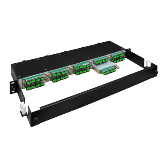
INSTALLATION OF 3400 SERIES MODULES The 3400 series passive optical module is designed to be housed in the 3400FR 1RU frame or 3400FR standalone. In the 3400FR, up to ten 3400 series passive optical modules can be securely housed in a 3400FR frame via a thumb screw. -
Page 24: Installing The 3400Cwdm
3400 Series Coarse WDM Optical Modules 3.1. INSTALLING THE 3400CWDM The 3400CWDM modules are available in a Multiplexor and Demultiplexor version. For optimum insertion loss characteristics, it is important to install a Multiplexor version at one end of the fiber link and a Demultiplexor version at the other end. -
Page 25: Specifications
3400 Series Coarse WDM Optical Modules SPECIFICATIONS 4.1. OPTICAL INPUT/OUTPUT Connector: LC/PC or LC/APC Wavelength: 3400DS2-4 1260 to 1610 nm 3400DS4-2 1260 to 1610 nm 3400DS8 1260 to 1610 nm 3400MS2-4 1260 to 1610 nm 3400DS4-2 1260 to 1610 nm... -
Page 26: Physical
3400 Series Coarse WDM Optical Modules 4.2. PHYSICAL 3400FR mounting: Number of slots: Page - 16 Revision 0.1...
Need help?
Do you have a question about the 3400 Series and is the answer not in the manual?
Questions and answers