Table of Contents
Advertisement
Quick Links
Advertisement
Table of Contents

Related Manuals for NI NI-9853


Summary of Contents for NI NI-9853
- Page 1 NI-9853 2022-07-06...
-
Page 2: Table Of Contents
Connecting a CAN Bus to the NI-9853........ -
Page 3: Overview
Safety Guidelines for Hazardous Locations The NI-9853 is suitable for use in Class I, Division 2, Groups A, B, C, D, T4 hazardous locations; Class I, Zone 2, AEx nA IIC T4 and Ex nA IIC T4 hazardous locations; and nonhazardous locations only. - Page 4 II 3G and is suitable for use in Zone 2 hazardous locations, in ambient temperatures of -40 °C ≤ Ta ≤ -70 °C . If you are using the NI-9853 in Gas Group IIC hazardous locations, you must use the device in an NI chassis that has been evaluated as Ex nC IIC T4, Ex IIC T4, Ex nA IIC T4, or Ex nL IIC T4 equipment.
-
Page 5: Emc Guidelines
Furthermore, any changes or modifications to the product not expressly approved by NI could void your authority to operate it under your local regulatory rules. Notice To ensure the specified EMC performance for the NI-9853, you must install clamp-on ferrite beads (NI part number 711849-01) in accordance with the product installation instructions. -
Page 6: Wiring The Ni-9853
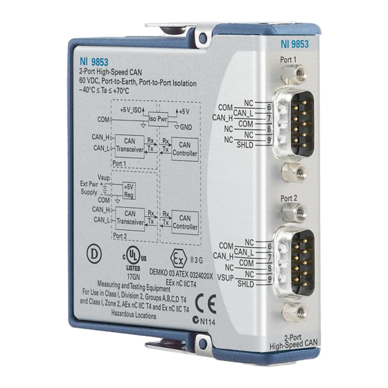
The NI-9853 has two 9-pin male D-Sub connectors that provide connections to a CAN bus. Each port on the NI-9853 has pins for CAN_H and CAN_L, to which you connect the CAN bus signals. Connect these signals using twisted-pair cable. -
Page 7: Can Bus Topology And Termination
NI-9853 Pinouts for CAN0 and CAN1 of the NI-9853 are listed in Tables 1 and 2. Table 4 lists recommended termination resistor values. Connector Pin Signal No Connection (NC) CAN_L SHLD CAN_H Table 1. Pin Assignments for CAN0 Connector Pin Signal... -
Page 8: Connecting A Can Bus To The Ni-9853
Node Connecting a CAN Bus to the NI-9853 You can connect each port of the NI-9853 to any location on a CAN bus. Figure 2 shows one example of connecting CAN0 of the NI-9853 directly to one CAN node, and CAN1 directly to another CAN node. CAN1 requires an external power supply on the CAN bus. -
Page 9: Termination Resistors
30 nodes to the bus. You can connect higher numbers of nodes if the nodes’ electrical characteristics do not degrade signal quality below ISO 11898 signal level specifications. The NI-9853 electrical characteristics allow at least 110 CAN ports on a network. © National Instruments... -
Page 10: Ni-9853 Hardware Overview
The NI-9853 has two full-featured, independent CAN ports that are isolated from each other, and from the other modules in the system. Each port or the NI-9853 has a Philips SJA1000 controller that is CAN 2.0B-compatible and fully supports both 11- bit and 29-bit identifiers. -
Page 11: Power Requirements
NI-9853 Note Contact NI for Bellcore MTBF specifications at other temperatures or for MIL-HDBK-217F specifications. Power Requirements Power consumption from chassis Active Mode Transmitting 625 mW max Receiving 400 mW max Sleep mode 25 µW max Thermal dissipation (at 70 °C) -
Page 12: Hazardous Locations
Note Do not connect the NI-9853 to signals or use for measurements within Measurement Categories II, III, or IV. The maximum voltage that can be applied or output between any port or V terminal and a COM terminal without creating a safety hazard. -
Page 13: Electromagnetic Compatibility
NI-9853 EN 60079-0:2012, EN 60079-15:2010 ■ IEC 60079-0: Ed 6, IEC 60079-15; Ed 4 ■ UL 60079-0; Ed 5, UL 60079-15; Ed 3 ■ CSA 60079-0:2011, CSA 60079-15:2012 ■ Note For UL and other safety certifications, refer to the product label or Online Product Certification section. -
Page 14: Ce Compliance
Refer to the product Declaration of Conformity (DoC) for additional regulatory compliance information. To obtain product certifications and the DoC for this product, visit ni.com/certification, search by model number or product line, and click the appropriate link in the Certification column. -
Page 15: Environmental Management
NI is committed to designing and manufacturing products in an environmentally responsible manner. NI recognizes that eliminating certain hazardous substances from our products is beneficial to the environment and to NI customers. For additional environmental information, refer to the Minimize Our Environmental Impact web page at ni.com/environment. -
Page 16: Worldwide Support And Services
Worldwide Support and Services The National Instruments website is your complete resource for technical support. At ni.com/support, you have access to everything from troubleshooting and application development self-help resources to email and phone assistance from NI Application Engineers. Visit ni.com/services for NI Factory Installation Services, repairs, extended warranty, and other services.
Need help?
Do you have a question about the NI-9853 and is the answer not in the manual?
Questions and answers