
Related Manuals for Asus PA246Q


Summary of Contents for Asus PA246Q
- Page 1 Service Manual PA246Q LCD Monitor Service Manual Model: PA246Q V 1.0 RESTRICTIONS ON USE OF MATERIALS:...
-
Page 2: Important Safety Notice
NOT EXHAUSTIVE. ASUS could not possibly know, evaluate and advise the service trade of all conceivable ways in which service might be done or of the possible hazardous consequences of each way. Consequently, ASUS has not undertaken any such broad evaluation. Accordingly, who uses a service procedure or tool which is not recommended by ASUS must first satisfy himself thoroughly that neither his safety nor the safe operation of the equipment will be jeopardized by the service method selected. -
Page 3: Monitor Specifications
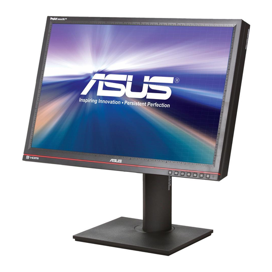
1 Monitor Specifications 1.1 Introduction This specification describes ASUS PA246Q, a 24” Wide multi-interface (Analog +DVI +HDMI +DisplayPort) color TFT LCD monitor. The display supports up to 1920*1200/60 Hz resolution & refresh rate and 1.07 billion colors (HDMI & DP).The features summary is shown below,... - Page 4 Service Manual PA246Q Press and hold “Splendid-key” for 2 ~ 4 Auto adjustment function supported seconds DDC function supported (EDID ver.1.3) DDC2B DDC-CI support version 1.1 or later DDC-CI Audio speakers supported Audio Jack (input connector) supported Earphone Jack (output...
- Page 5 Service Manual PA246Q 1.3 Weight Item Condition Spec OK N.A Remark √ Monitor (Net) +/- 4% 7.3 kg √ Monitor with packing (Gross) 10 kg + 5% 1.4 Plastic Item Condition Spec OK N.A Remark √ Flammability 94 HB √...
-
Page 6: Video Performance
Service Manual PA246Q 2 Operation Instructions 2.1 Video performance Item Condition Spec N.A Remark Any input resolution modes √ Resolution which under 1920 x1200@60Hz 1920x1200 √ Contrast ratio 1000:1(typ.) At R B saturated 、 、 270 cd/m (typ.) √ Brightness... -
Page 7: Electrostatic Discharge Requirements
Service Manual PA246Q 2.5 Transportation Item Condition Spec N.A Remark √ Vibration Unpacked, Non-Operating 20 Hz, 0.0185 g 200 Hz, 0.0185 g (Duration: 5 min Per AXIS) √ Package Test √ (1)Random Vibration Package, Non-Operating 1Hz, 0.0001 g 4 ~100 Hz, 0.0001 g 200 Hz, 0.001 g... -
Page 8: User's Hardware Control Definition
Service Manual PA246Q 2.8 User’s hardware control definition:... - Page 9 Service Manual PA246Q 2.9 OSD control function definition Item File Name Graphic Related OSD Comment ButtonTypeC_F_L.png This will be used in those OSD for CI module. (Suggest : Do not change) ButtonTypeC_F_M.png This will be used in those OSD for CI module(Suggest : Do not change) ButtonTypeC_F_R.png...
- Page 10 Service Manual PA246Q menu_info_notice.bmp menu_button.bmp menu_lock.bmp menu_lock_hide.bmp menu_time.bmp menu_channel.bmp menu_channel_hide.b mp menu_option.bmp menu_picture.bmp menu_audio.bmp volume_ball_blue.bmp volume_ball_gray.bmp volume_ball_purple.bm volume_ball_purple_hid e.bmp...
- Page 11 Service Manual PA246Q bmp_bubbles.bmp volume_ball_gray.bmp volume_ball_gray_hide. triangle_down.bmp arrow_down_1.bmp arrow_down_2.bmp arrow_up_1.bmp arrow_up_2.bmp arrow_left_1.bmp arrow_left_2.bmp arrow_right_1.bmp arrow_right_2.bmp ball_yellow_down.bmp ball_yellow_bg_up.bmp ball_gen_bg_up.bmp ball_gen_bg_down.bmp ball_green_bg_up.bmp ball_green_bg_down.b ball_blue_bg_up.bmp ball_blue_bg_down.bm p arrow_down_1.bmp arrow_down_2.bmp arrow_up_1.bmp arrow_up_2.bmp arrow_left_1.bmp arrow...
- Page 12 Service Manual PA246Q ball_bg.bmp manual_scan_icon.bmp bmp_bubbles2.bmp ball_blue_bg_up.bmp ball_blue_bg_down.bm ball_green_bg_down.b Red (207, 49, 48) Yellow (254, 203, 92) ball_green_bg_up.bmp Green (166, 174, 122) ball_red_bg_up.bmp Blue(213, 89, 43) ball_red_bg_down.bmp ball_yellow_bg_up.bmp ball_yellow_bg_down.b ball_gen_bg_down.bmp ball_gen_bg_ list_Bubble.bmp list_Bubble_R.bmp list_bar_M.bmp list_bar_R.bmp...
- Page 13 Service Manual PA246Q 1. Please refer to Item24 for the title bar on the up. 2. Please refer to Item 19 21 list_Bubble_source.bmp for the bottom of the OSD 1. Please refer to Item24 for the title bar on the up. 2. Please refer to Item 19 list_Bubble_info.bmp...
-
Page 14: Input/Output Specification
Service Manual PA246Q 3 Input/Output Specification 3.1 Power supply Item Condition Spec OK N.A Remark √ Input Voltage range Universal input full range 100-240V, 50/60 Hz √ Input Current range 100 ~ 240VAC < 2 Arms √ Normal “On” operation <... - Page 15 Service Manual PA246Q Logic High: 2.0V ~ 5.5V Refer to VESA VSIS √ Level Logic Low: 0V ~ 0.8V (TTL level) Standard V1R1 √ Impedance Minimum 2.2K (pull down) 2.2K for application √ Level 600mV for each differential line Digital input 100 Ohm TDR Scan needed for √...
- Page 16 Service Manual PA246Q DDC Data TMDS Ground Floating TMDS RX5- TMDS RX1- TMDS RX5+ TMDS RX1+ TMDS Ground TMDS Ground TMDS Clock+ TMDS RX3- TMDS Clock- Note 3: Type A (Receptacle) HDMI HDMI Digital connector pin assignments MNEMONIC SIGNAL TX 2 +...
-
Page 17: Scan Range
Service Manual PA246Q Signal Assignment Signal Assignment Lane0 P Ground Lane3 N Ground Lane0 N Ground Lane1 P EDID WP Ground AUX_CH P Lane1 N Ground Lane2 P AUX_CH N Hot Plug Detect Ground Lane2 N Return Lane3 P DP_PWR 3.3 Input Video Signal Performance Requirement... -
Page 18: Support Timings
Service Manual PA246Q 3.6 Support Timings VGA+DVI+HDMI (PC) Horizontal Dot Clock Actual display OK N.A Remark Input Timing Vertical Frequency Frequency Resolution Resolution Frequency (Hz) (KHz) (MHz) √ 1920x1200 640x480 31.47(N) 59.94(N) 25.18 √ 1920x1200 640x480 35.00(N) 66.66(N) 30.24 Macintosh √... -
Page 19: Block Diagram
4 Block Diagram 4.1 Function block PA246Q is a 24” WUXGA (1920x1200) resolution TFT LCD monitor. The monitor shall support VGA, DVI, Displayport and HDMI with HDCP inputs. Moreover, PA246Q equips headphone out to enhance its features and one USB upstream, two USB inputs and card reader. It’s compliant with VESA specification to offer a smart power management and power saving function. - Page 20 Service Manual PA246Q functions. A/D converter converts analog signal to digital data. OSD is offering adjustable functions to end-user. Detect timing is for detect change mode. Scalar generates the pixel clock to the T-CON. Finally output the digital RGB data, the Hsync, Vsync and pixel clock to LCD panel driver IC.MCU offers H/W DDC2BI function &...
- Page 21 Service Manual PA246Q #2 Converter Circuit – L4978 The L4978 is a step down monolithic power switching regulator delivering 2A at a voltage between 3.3V and 50V (selected by a simple external divider). Realized in BCD mixed technology, the device uses an internal power D-MOS transistor (with a typical R of 0.25 ) to obtain very high efficiency...
-
Page 22: Schematic Diagram
Service Manual PA246Q 5 Schematic Diagram 5.1 Power Board... -
Page 23: Control Board
Service Manual PA246Q 5.2 Control Board... -
Page 24: Interface Board
Service Manual PA246Q 5.3 Interface Board... - Page 25 Service Manual PA246Q...
- Page 26 Service Manual PA246Q...
- Page 27 Service Manual PA246Q...
- Page 28 Service Manual PA246Q...
-
Page 29: Pcb Layout
Service Manual PA246Q 6 PCB layout 6.1 Power Board... - Page 30 Service Manual PA246Q 6.2 Control Board 6.3 Interface Board...
-
Page 31: Color/White Balance Adjustment
Service Manual PA246Q 10 Color/White balance Adjustment Alignment procedure (for function adjustment) A list of necessary alignments for the LCD monitor: Items Description Remark Timing adjustment Preset timing Auto color balance adjustment Timing 114 VGA 480 640x480@60Hz or Timing 118... - Page 32 Service Manual PA246Q 1. Setup input timing to any preset modes, pattern 41(full white color pattern) with Analog signals from Chroma video pattern generator. 2. Enter factory mode (Press menu key and up key then press power key, hold on about 2 sec will enter the factory mode.).
-
Page 33: Troubleshooting
Service Manual PA246Q 11 Trouble Shooting 11.1 No Display or display is unstable (Interface Board): Screen is Blank and Power LED is white. Follow instructions from OSD dialog OSD shown when key pressed? Proceed to “Check Control Board”. Keypad OK? Proceed to “Check Power Board”. - Page 34 Service Manual PA246Q 11.2 Check Control Board Checking Control Board Plug control board then retry Is control BD connecting? Replace a new control board, then control board PCB retry Replace the components, then Is botton key normally? retry Check interface board Scalar...
- Page 35 Service Manual PA246Q 11.3 Check Scalar:...
- Page 36 Service Manual PA246Q 11.4 Check LCD Module:...
- Page 37 Service Manual PA246Q 11.5 USB Hub (Upstream/Downstream Port) / Card reader does not work: Check LDO regulator voltage to 5V is correctly received and correctly convert to 3.3V & 1.2V Further more, for the abnormal USB port, power line of this USB port is advised to check.
- Page 38 Service Manual PA246Q 11.6 Check Inverter BD: Check Inverter Check CN801 Pin 6 (BL_ON) Check Power BD & I/F BD Voltage ≈ 3.3V (High) Check CN801 Pin 7 (BL_ADJ) Voltage ≈ 3.3V (High) Check Power BD & I/F BD or PWM Signal...
- Page 39 Service Manual PA246Q 11.7 Check Power BD: Check Power BD Check CN801 Pin 1~5 Check F701 & F702 Replace F701 & F702 Voltage ≈ 24V Check Q701 & Q702 & IC701 Replace Q701 & Q702 & IC701 Check V-IF +5V Check Q852 &...
- Page 40 Service Manual PA246Q 11.8 Check PFC Function:...
- Page 41 Service Manual PA246Q 12 Exploded View...
- Page 42 Service Manual PA246Q...
-
Page 43: Recommended Parts List
Tape 3H.04054.071 TAPE ADHESIVE 35*25 BLK 7651F TRIVIAL Label_SPEC 4E.0VU01.041 LBL SPEC 88*28 PA246 WW TRIVIAL Label_Prevent 4E.L4603.051 LBL PREVENT 30*15 ASUS VH226H TRIVIAL Label 4E.0KM04.001 LBL BLANK 43*14 WHITE TRIVIAL Screw 8F.00551.3R0 SCRW M FPH M2*3L (6/1.4) NI TRIVIAL Screw 8F.205B4.019... - Page 44 CORD VCTF7A125V 1.8M JAN DELL ACCESSORY Warranty Card_EU 4J.17Y03.001 WARRANTY ASUS EU NONZBD LCD ACCESSORY Warranty Card_AP 4J.17Y02.001 WARRANTY ASUS AP NON ZBD LCDED ACCESSORY Warranty Card_TW 4J.17Y05.001 WARRANTY ASUS TW NONZBD LCDLED ACCESSORY Warranty Card_NA 4J.17Y04.001 WARRANTY ASUS NA NONZBD LCD...
- Page 45 Service Manual PA246Q Photos of Recommended Parts List...
-
Page 46: Different Parts List
Service Manual PA246Q 14 Different Parts List RECOMMENDED SPARE PARTS LIST (RSPL) Asus Model : PA246 Vendor 9J.18R72.QL1/9J.18R72.QL2/9J.18R72.QL3/9J.18R72.QL5/9J.18R72.QLJ Model: Type Subset Vendor P/N Vendor Description Usage MOQ 9J.18R72.QL1 9J.18R72.QL2 9J.18R72.QL3 9J.18R72.QL5 9J.18R72.QLJ DISPLAY PANEL(LGD) 5F.LLDUP.011 LCDM24W LM240WU4-SLB3 LGD P ELECTRICAL MAIN BOARD(LGD) 5E.18R01.001... - Page 47 CORD VCTF 7A125V 1.8M CNS-TW ACCESSORY Power Cord_JAN 2G.03515.021 CORD VCTF7A125V 1.8M JAN WARRANTY ASUS EU NONZBD ACCESSORY Warranty Card_EU 4J.17Y03.001 WARRANTY ASUS AP NON ZBD ACCESSORY Warranty Card_AP 4J.17Y02.001 LCDED WARRANTY ASUS TW NONZBD ACCESSORY Warranty Card_TW 4J.17Y05.001 LCDLED...
- Page 48 15 Substitution Parts List NONE 16 BOM List Level Component Description Qty Per 5G.18R72.QL1 5G PA246Q LGDEU 1A1D1H1DP USB 1 PC 5E.18R01.001 PCBA IF BD MI PA246 1 PC ...3 0J.10612.089 # CAP EL 10U 25V M RF2 5*11 6 PC ...3...
- Page 49 Service Manual PA246Q ..4 6C.R0032.111 #CHIP RES 0 J 1/4W 1206 1 PC ..4 6C.R0033.151 #CHIP RES 0J 1/10W 0603 6 PC ..4 6C.R0034.1D1 #CHIP RES 0 J 1/16W 0402 31 PC ..4 6D.10035.551 #CHIP RES 100K F 1/10W 0603 1 PC ..4...
- Page 50 Service Manual PA246Q ...3 1A.2241N.11E CAP X 0.22U U/V/FI 275V CC15 1 PC ...3 1A.4742U.04E CAP PS 0.47U 520V K CC15 2 PC ...3 1C.68335.07E #RES MOFM 68K J 2W AKF15 MINI 1 PC ...3 1C.R1035.07F RES MOFM 0.1 2W J AF15 MINI 2 PC ...3...
- Page 51 Service Manual PA246Q ..4 6D.33025.161 #CHIP RES 33K F 1/8W 0805 2 PC ..4 6D.33235.411 CHIP RES 332K F 1/4W 1206 1 PC ..4 6D.42225.161 CHIP RES 42.2K F 1/8W 0805 1 PC ..4 6D.47015.161 #CHIP RES 4.7K F 1/8W 0805 1 PC ..4...
- Page 52 1 PC ..4 8C.00099.E11 DIODE SW.215A75V BAV99 SOT23 4 PC ...3 5K.18R05.001 WIRE 7/11P #28 PA246 1 PC GC.18R72.QL1 DC PA246Q LGDEU 1A1D1H1DP USB 1 PC ...3 3D.18R02.001 SHD USB PA246 1 PC ...3 3H.04054.071 TAPE ADHESIVE 35*25 BLK 7651F 1 PC ...3...
- Page 53 8F.VG434.6R0 #SCRW TAP PH W/F M3*6TP-S ZN 11 PC ...3 8F.VZ524.6R0 SCRW TAP FLAT+EXT M3*6L C-ZN 1 PC GP.18R72.QL1 DP PA246Q LGDEU 1A1D1H1DP USB 1 PC 2G.00921.001 CORD H05VV-F 10A250V EUR 1.8M 1 PC 3H.04605.482 TAPE 0.055*60*900M 3M373 ASUS 1.7875 M 3H.11001.001...
-
Page 54: Appendix 1 - Screw List / Torque
Service Manual PA246Q 17 Appendix 1 – Screw List / Torque (A) STANDARD SCREW TORQUE SPEC for QCS MOUNTING TORQUE HOLE SIZE Screw ITEM DESCRIPTION MATERIAL (KG-CM) (MM) Head Metal; 8F.205B4.019 SCRW MACH HEX #4-40*0.3" N D-SUB;DVI 5.0±0.6 5.0±0.6 #4-40... - Page 55 Service Manual PA246Q Metal 8F.XA324.5R0 SCRW TAP M3*5L B-ZB 2.85~2.95 Metal to Plastic Metal 8F.1A526.5R0 SCRW MACH PAN M4*5L NI Metal to metal 8~10 M4*0.7P Plastic to metal Metal 8F.1B524.3R0 SCRW MACH PAN W/SPG M3*3L NI Metal to metal M3*0.5P...
- Page 56 Service Manual PA246Q (B)STANDARD SCREW TORQUE SPEC for SKD site Part NO. Description torque Size Screw head 10.5±1.0 8F.00524.8R0 SCRW M FH M4*8L(D7.5)B-ZN NYL 8F.5A256.8R0 SCRW MACH FH M4*8L ZN NYL 10.5±1.0 8F.5A356.100 SCRW MACH FH M4*10L B-ZN NYL 10.5±1.0 8F.5A356.120...
Need help?
Do you have a question about the PA246Q and is the answer not in the manual?
Questions and answers