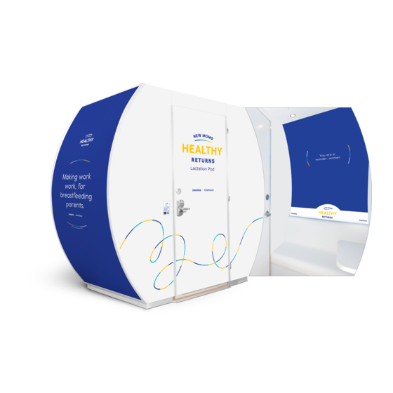
Summary of Contents for Mamava XL
- Page 1 XL Assembly Instructions People required: 2 Average time required: 4 hours For replacement parts, questions or concerns, contact: 802.347.2111 service@mamava.com Version: XL V4 02/25/2022 Page 1...
- Page 2 Page 2...
- Page 3 Table of Contents Header and Roof Pans (Page 11) Floor Pan (Page 5) Step 25..Step 1..Step 26..Step 2..Step 27..Step 28..Seats and Counters (Page 6) Step 29..Step 3..Step 4..Wiring: Roof Pan (Page 12) Step 5..
- Page 4 PARTS LIST LOOSE HARDWARE (8) M8 X 1.25 X 16mm Flat-head Screw PART NUMBER DESCRIPTION (57) M8 X 1.25 X 25mm Flat-head Screw XL-A101 FRONT FLOOR PAN (40) M8 X 1.25 X 50mm Flat-head Screw F110 XL-A103 BACK FLOOR PAN (8) #8 X 3/4"...
- Page 5 Note: If this is a seismic unit, follow the instructions included FLOOR PAN in the seismic kit before continuing to step 1 of this document. 1. Set parts on floor as shown. 2. Fasten Front Floor Pan and Back Floor Pan flanges to Left and Right Chassis.
- Page 6 SEATS AND COUNTERS MIDDLE COUNTER E600 LEFT COUNTER 3. Fasten bottom of Left Outlet Box to top of Left Chassis, E400 and bottom of Right Outlet Box to top of Right Chassis. RIGHT COUNTER E500 (2 per side) M8 X 1.25 X 25mm screws 4.
- Page 7 BACK WALL PANELS 9. Hook Back Middle Wall BACK LEFT WALL PANEL Panel onto back of Middle Counter. D300 10. Hook Back Left Wall Panel onto top of Left Chassis. BACK MIDDLE WALL PANEL 11. Hook Back Right Wall Panel D500 onto top of Right Chassis.
- Page 8 BACK LEFT WALL PANEL D300 OUTLET BOXES AND COUNTERS BACK MIDDLE WALL PANEL D600 14.Fasten Middle Counter to Back Middle Wall Panel. (2) M8 X 1.25 X 50mm screws BACK RIGHT WALL PANEL D400 15. Fasten Chassis to Back Wall Panel, both sides. (4 per side) M8 X 1.25 X 25mm screws MIDDLE COUNTER E600...
- Page 9 WIRING: OUTLET BOXES 17. Feed GFCI Wire through Middle Counter and Left counter holes. Connect to Left J-Box. 18. Feed Right J-Box Wire out through Right Counter, Middle Counter, and Left counter. Connect to Left J-Box. PCD POWER CORD 19. Feed PCD power cord through Middle Counter and Left Counter.
- Page 10 FRONT WALL PANELS 21. Hook Front Left Wall Panel onto top of Left Chassis. FRONT LEFT WALL PANEL D100 22. Hook Front Right Wall Panel onto top of Right Chassis. 23. Fasten Chassis to Front Wall Panel, both sides. (4 per side) M8 X 1.25 X 25mm screws 24.
- Page 11 BACK ROOF PAN F101 HEADER AND ROOF PANS 25. Pop Header Brackets into Wall Panel Bracket Slots by pushing downard on Header. Rotolock Header to Front Left SIDE ROOF PAN F102 SIDE ROOF PAN Wall Panel and Front Right Wall Panel with provided allen key. F102 26.
- Page 12 WIRING: ROOF PAN 30. Connect Rear Wire Harness into the Single and Y Lead Harnesses, respectively. SINGLE LEAD REAR WIRE HARNESS WIRE HARNESS 31. Connect Front Fan Wire to Y Lead Harness. 32. Connect Front Wall Panel Wires to Single and Y Lead Harnesses, respectively PCD POWER CORD 33.
- Page 13 BEAUTY PANELS 35. **If unit needs to be moved, raise leveling feet located in bottom corners of the Chassis (red painted bolts). Once unit is in the right spot, level it in both directions with 9/16" socket wrench and 2' Level** 36.
- Page 14 GRAPHIC PANELS AND ROOF CAPS GRAPHIC CAP F104 38. Place ladder inside unit. Feed Graphic PERF PAN Panel overhead and into slots in the F109 Wall Panel Channels, both sides. 39. Drop both Roof Caps onto Roof Pans as shown. GRAPHIC CAP F104 PCD antennas pass through holes in Roof Cap.
- Page 15 DOOR DOOR FRAME BRACKET 42. Hang Door and connect door closer arms. F111 DOOR FRAME BRACKET F111 43. Adjust Door Kick so that it sits 1" off the floor. Tighten in place via screws on back of door. 44. Fasten Door Frame Brackets to top and inside of unit as shown in Detail D and D1.
- Page 16 (OPTIONAL FRIDGE CABINET INSTRUCTIONS) MIDDLE COUNTER FRIDGE CABINET/SEAT AND COUNTERS E600 LEFT COUNTER E400 3. Fasten bottom of Left Outlet Box to top of Left Chassis, and bottom of Right Outlet Box to top of Right Chassis. Remove Right J-Box from Right Outlet Box. (2 per side) M8 X 1.25 X 25mm screws RIGHT COUNTER E500...
- Page 17 (OPTIONAL FRIDGE CABINET INSTRUCTIONS) WIRING: FRIDGE CABINET AND OUTLET BOX 18. Feed Fridge Cabinet Wire out through Right Counter, Middle Counter, and Left counter. Connect to Left J-Box. Note: Return to Page 10 after completing these steps. FRIDGE CABINET WIRE LEFT LEFT COUNTER J-BOX...
- Page 18 By signing the below, certifies the understanding and satisfaction with the pod(s) installation. Any installation changes and/or requests submitted to Mamava post installation may be subject to service fees. Mamava.com...


Need help?
Do you have a question about the XL and is the answer not in the manual?
Questions and answers