
Related Manuals for Mamava Flex V1.0


Summary of Contents for Mamava Flex V1.0
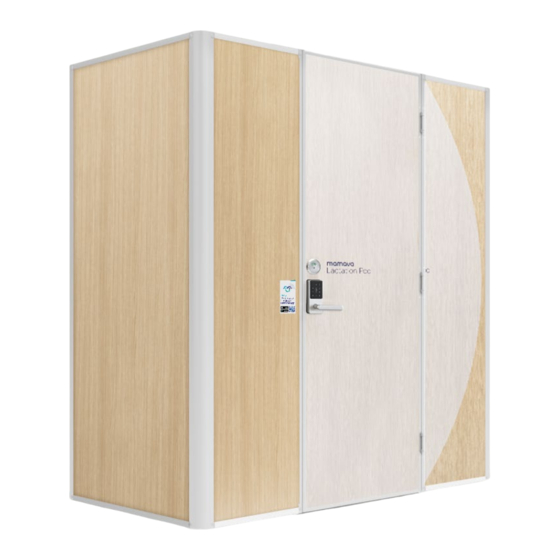
- Page 1 Flex V1.0 Assembly Guide service@mamava.com (802) 347-2111 Watch the assembly video Updated: 12/18/2022...
-
Page 2: Table Of Contents
Assembled pod dimensions: 6'7" W x 3'8" D x 7'9" H (includes pod and antenna) Minimum ceiling clearance required for assembly: 7'9" It should take 2 people approximately 2 hours to assemble this Mamava pod. Table of Contents Tools + Hardware............................................3 Parts .................................................. -
Page 3: Tools + Hardware
Tools + Hardware Not included Label Maker (or Cordless Drill Light Working Gloves Box Cutter Tape Measure with #2 Phillips Bit* Permanent Marker) *For crate disassembly only Ratchet + 2-6' Step Ladder Outlet Tester Flat Head Screwdriver Phillips Head #2 Screwdriver 9/16"... -
Page 4: Parts
Parts PA R T N U M B E R PA R T PA R T N U M B E R PA R T 15450 Power Cord 19675 Door 19310 Rail, Bottom, Wall Panel 19685 Floor 19315 Wire Cover 19690 Wall Panel, Front Left 19370... -
Page 5: Warnings
Warnings To reduce the risk of electrical shock: Always unplug this furnishing from the electrical outlet before cleaning or servicing. Only connect the power cord to a properly grounded outlet. Do not use the pod if you notice any defects to electrical equipment. To reduce the risk of burns, fire, electric shock or injury to persons: Read and understand the assembly guide and all safety To disconnect, turn all controls to the off position, then... -
Page 6: Markings
Markings WARNING Risk of fire and shock Use only SJ00W type 12 AWG cord AVERTISSEMENT Risque d’incendie et de choc électrique Utilisez uniquement un cordon SJ00W de grosseur 12 AWG 2.7234” W X 1.9228” H WARNING WARNING Risk of tip over Risk of tip over Max 80 lb. -
Page 7: Shipping Crate
Shipping Crate T O O L S A N D P A R T S • Cordless Drill with a #2 Phillips Bit 1. Use a cordless drill with a #2 Phillips bit to remove the screws from the crate cross braces. 2. -
Page 8: Foundation
• Tape Measure • Shelf (19630) • 5 mm Hex Key (19680) Find an even and level surface for the Mamava Flex and assemble it as close as possible to its final location. 1. Unpack the floor (19685) from Box 4 and place it (vinyl side up) where the pod will be assembled. - Page 9 Front 3. Unpack the main power cord from Box 1. Lift the back of the chassis and insert approximately 12” of the receptacle end under the flange at the back of the left side chassis. You’ll connect the power cords later.
-
Page 10: Back Wall Panels
Back Wall Panels T O O L S A N D P A R T S • Box Cutter • Wall Panel, Back Left (19735) • (8) M8-1.25 x 30 Button Head • Rail, Bottom, Wall Panel Cap Screws (19135) (19310) •... - Page 11 4. Unpack the back right wall panel (19715) from Box 2. With the white side of the panel and mirror facing the interior, place the panel into the chassis channel and the wall panel bottom rail. Push the panel against the back left wall panel.
- Page 12 6. Unpack the wall panel top rail (19745) from Box 5. Center it onto the back wall panels with the fan and PCD facing the interior. Loosely fasten the rail to the wall panels with (4) M8-1.25 x 30 button head cap screws (19135).
- Page 13 8. Connect the power supply harness to the power supply in the left side of the shelf. Ensure all cords are tucked inside the shelf. 9. Guide the receptacle end of the main power cord up into the left side of the shelf. 10.
-
Page 14: Side Wall Panels
Side Wall Panels T O O L S A N D P A R T S • Box Cutter • Wall Panel, Left (19645) • Flat Head Screwdriver • Wall Panel, Right (19615) • (4) M8 x 55 Flange Head Bolts (16370) •... - Page 15 3. Fasten the left side wall panel to the chassis with (4) M8-1.25 x 40 button head cap screws (19875). If the bolt doesn’t thread easily into the wall panel, you may need to adjust the alignment. Tighten the screws with the 5 mm hex key.
- Page 16 5. Use a flat head screwdriver to fasten the right side wall panel to the base and back wall panel with (2) M8 x 55 flange head bolts (16370). Start at the top to stabilize the panel. 6. Loosely fasten the right side wall panel to the chassis with (4) M8- 1.25 x 40 button head cap screws (19875).
-
Page 17: Front Wall Panels + Door
Front Wall Panels + Door T O O L S A N D P A R T S • Box Cutter • 5 mm Hex Key (19680) • Wall Panel, Front Left (19690) • Flat Head Screwdriver • (2) M8-1.25 x 30 Button Head •... - Page 18 3. Use a flat head screwdriver to fasten the front left wall panel to the left side wall panel with (2) M8 x 55 flange head bolts (16370). Start at the top to stabilize the panel. If the bolt doesn’t thread easily into the wall panel, you may need to adjust the alignment.
- Page 19 5. Unpack the door (19675) with attached right front wall panel (19700) from Box 1. Carefully remove the tape securing the panel to the door. The springs in the hinges will open the panel to align with the door. At this point It’s helpful to turn the deadbolt latch on the inside of the door to keep the door from closing.
- Page 20 7. Use a flat head screwdriver to fasten the right front wall panel to the right side wall panel with (2) M8 x 55 flange head bolts (16370). Start at the top to stabilize the panel. It’s helpful to have a second person assist with alignment.
- Page 21 9. Unwind the plunger cable at the top of the front left wall panel. Unpack the header rail (19370) from Box 5. Push the plunger cable through the grommet in the front side of the header rail. Position the header rail on top of the front panels.
- Page 22 11. Use a flat head screwdriver to fasten the front right wall panel and the front left wall panel to the header with (2) M8 x 55 flange head bolts (16370). Tighten the (6) header screws with the 5 mm hex key.
-
Page 23: Wiring Connections
Wiring Connections T O O L S A N D P A R T S • Ladder 1. Uncoil the wires at both corners of the left side wall panel. 2. Connect the two wires at the top of the front left wall panel. - Page 24 3. Connect the two wires at the back left corner. 4. Connect the wires in the middle of the left side back wall panel. 5. Connect the two wires at the back right corner.
-
Page 25: Interior + Roof Panel
Interior + Roof Panel T O O L S A N D P A R T S • Box Cutter • (4) M8-1.25 x 30 Button Head • Wire Cover (19315) • Phillips Head Screwdriver Hex Drive Screw (19135) • Seat Back (19545) •... - Page 26 3. Unpack the seat base (19540) from Box 4 and place it at a 45° angle over the left side chassis. Press down into place. 4. Use a Phillips head screwdriver to fasten the seat base to the chassis with (4) 1/4-20 X 2” pan head Phillips screws (16870).
- Page 27 5. Unpack the bench top (19625) from Box 4 and place it a 45° angle over the right side chassis. The wood side should face the back. Press into place. 6. Loosely fasten the bench top to the right side chassis with (4) M8-1.25 x 30 button head hex cap screws (19135).
- Page 28 The roof material smudges easily, so wash hands before handling it. 7. Unpack the roof (19620) from Box 4. Place a ladder outside the front of the pod to access the top. It’s helpful to have someone pass you the roof and position it on the side panel.
-
Page 29: Moving + Leveling
Moving + Leveling T O O L S A N D P A R T S • Ratchet and 9/16" Socket If you assembled the pod in its final location, you’re ready to lower the leveling feet. If you need to move it to its final location, hold the power cord up off the floor and, with help from another... - Page 30 2. Turn the deadbolt lever to retract it fully into the door and shut the door. Press 8008# on the keypad to open the door. Open and close the door a few times to check for proper alignment. There should be an even gap along the latch side of the door.
-
Page 31: Final Assembly + Testing
Final Assembly + Testing T O O L S A N D P A R T S • 5/32” Hex Key (provided) • (2) Beauty Panels (19730) • Outlet Tester • (2) Shelf Support Covers (19805) • Label Maker or Permanent Marker 1. - Page 32 If your pod doesn’t pass these final tests, be sure to visit our Help Center at help.mamava.com where you’ll find answers to questions about assembly, leveling, pod maintenance, and more. 4. Open the door using 8008# on the keypad.
- Page 33 6. Make sure the door latches, but doesn’t slam. If you need to increase the door closure speed, close the door and insert the 5/32” hex key in the top of the hinge, push down, and rotate clockwise. To decrease the door closure speed, rotate counterclockwise.
-
Page 34: Notes
D O N ’ T F O R G E T If this pod is being listed on the Mamava app—so breastfeeding parents can find the space using Mamava’s Smart Access—please send photos of your installed pod to customersuccess@mamava.com. Notes Need assistance? Visit help.mamava.com or contact service@mamava.com •...
Need help?
Do you have a question about the Flex V1.0 and is the answer not in the manual?
Questions and answers