Table of Contents
Advertisement
Quick Links
These instructions must be read thoroughly before installation or operation. This instruction manual was accurate at the time of
printing. Please see dodgeindustrial.com for updated instruction manuals.
WARNING: To ensure the drive is not unexpectedly started, turn off and
lock-out or tag power source before proceeding. Failure to observe these
precautions could result in bodily injury.
WARNING: Only qualified personnel familiar with hydraulic and electrical
installations, the construction and operation of this equipment, and the
hazards involved should install, adjust, operate, and/or service it. Read
and understand this manual in its entirety before proceeding. Failure to
observe this precaution could result in severe bodily injury or loss of life.
SYSTEM SPECIFICATIONS
System Part
Number
Motors Information
063488
Single Phase—115/230 VAC
063487
Three Phase—230/460 VAC
Three Phase—208-230/460 VAC
078289
(Explosion Proof Motors)
078290
Three Phase—575 VAC (Canada)
NOTE: For Cool Lube 2 Material Details, please refer to cut sheets.
Air to oil heat exchanger: Thermal Transfer BOL-8-2
* Pump Relief valve setting: 150 psi
* Bearing Relief valve setting: 65 psi
Pump flow rate: 2 GPM
Flow meter range: 0.5 – 4.0 GPM
Oil supply line connection:
Oil return line connection: Two 1" NPT connections (female)
* Relief valves are preset at the factory, but are field adjustable. If other
settings are required, consult Dodge Engineering
WARNING: Because of the possible danger to person(s) or property
from accidents which may result from the improper use of products,
it is important that correct procedures be followed. Products must be
used in accordance with the engineering information specified in the
catalog. Proper installation, maintenance and operation procedures
must be observed. The instructions in the instruction manuals must
be followed. Inspections should be made as necessary to assure
safe operation under prevailing conditions. Proper guards and other
suitable safety devices or procedures as may be desirable or as may
be specified in safety codes should be provided, and are neither
provided by Dodge
nor are the responsibility of Dodge. This unit and
®
its associated equipment must be installed, adjusted and maintained
by qualified personnel who are familiar with the construction and
Operation of all equipment in the system and the potential hazards
involved. When risk to persons or property may be involved, a holding
device must be an integral part of the driven equipment beyond the
speed reducer output shaft.
Cool Lube 2 for Sleevoil Pillow Blocks
Part Numbers 063487, 063488, 078289, 078290
Instruction Manual
Approximate
Weights (lbs)
Two 1/2" NPT connections at the
flow meter outlets (female)
WARNING: All products over 25 kg (55 lbs) are noted on the shipping
package. Proper lifting practices are required for these products.
RECEIVING & INSPECTION
1.
Carefully unpack the Cool Lube 2 system. Inspect the system
for any damage during shipping.
2.
Report any damage to the carrier for claims.
3.
Make sure that available voltage supply is within 10% of the
system voltage.
4.
Check all hydraulics to ensure that nothing came loose during
shipping. Tighten as needed.
5.
Changes to this unit may void the warranty.
257
257
257
257
FLOW
METERS
INSTALLATION
1.
Place the unit in the designated area and anchor it down
using the 4 mounting holes in the base plate. The unit should
be positioned below the circulating oil drain holes in the
bearings so that at least a 15° drain line slope is achieved to
allow for adequate oil return (see Figure 1).
2.
Make sure that there is enough space around the unit to allow
for servicing.
3.
Connect oil supply lines (not included) from the two 1/2" NPT
(female) outputs of the flow meters to the circulating oil inlets
on the housings. Connection details for each type of Sleevoil
bearing are provided in sections following (see Figure 2).
NOTE: All plumbing should be cleaned and flushed
before being connected to the bearings.
1
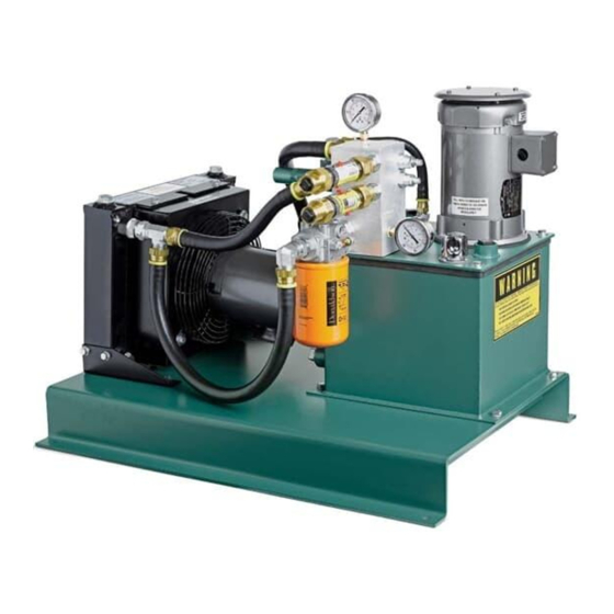
Figure 1 - Cool Lube 2
BEARING
PRESSURE
GAUGE
Figure 2 - Controls
NEEDLE
VALVES
PUMP
PRESSURE
GAUGE
Advertisement
Table of Contents

Related Manuals for Dodge Cool Lube 2


Summary of Contents for Dodge Cool Lube 2
- Page 1 (Explosion Proof Motors) 078290 Three Phase—575 VAC (Canada) NOTE: For Cool Lube 2 Material Details, please refer to cut sheets. Air to oil heat exchanger: Thermal Transfer BOL-8-2 Figure 1 - Cool Lube 2 * Pump Relief valve setting: 150 psi...
- Page 2 A Circulating Oil Inlet Kit is required for each pillow block for the screw. Check Table 1 to ensure that the bearings have the correct Cool Lube 2 installation. Install the Circulating Oil Inlet Kit as plunger screw. If replacement is necessary, install the new shown in the appropriate Sleevoil Instruction Manual.
- Page 3 A Circulating Oil Inlet Kit is required for each pillow block for the A Circulating Oil Inlet Kit is NOT required for these pillow blocks. Cool Lube 2 installation. Install the Circulating Oil Inlet Kit as The circulating oil inlets are machined into the housing and are shown in the Sleevoil Instruction Manual (see Figure 5).
- Page 4 Start the Cool Lube 2 and allow the oil to circulate. Be sure to circulating oil is off and the circulating oil drain holes are monitor the oil level in the tank to ensure that the oil returns open.
- Page 5 1/3 HP MN3082...
- Page 6 NOTE: Cool Lube 2 Units manufactured after September 2016 utilize a new relief valve for the pressure line only. Previous Relief Valve: Hydraforce RV08-20H-0-N-5/.75 New Relief Valve: Fulflo VJ-3R/HS/WS For Cut Sheets of each valve, contact manufacturers.
- Page 7 MN3082...
- Page 8 Dodge Industrial, Inc. *3082-0222* 1061 Holland Road Simpsonville, SC 29681 +1 864 297 4800 © DODGE INDUSTRIAL, INC. All Rights Reserved. Printed in USA. AN RBC BEARINGS COMPANY MN3082 02/22...
Need help?
Do you have a question about the Cool Lube 2 and is the answer not in the manual?
Questions and answers