Advertisement
Quick Links
These instructions must be read thoroughly before installation or operation. This instruction manual was accurate at the time of
printing. Please see dodgeindustrial.com for updated instruction manuals.
WARNING: To ensure the drive is not unexpectedly started, turn off and
lock-out or tag power source before proceeding. Failure to observe these
precautions could result in bodily injury.
WARNING: Because of the possible danger to person(s) or property from accidents which may result from the improper use of products, it is
important that correct procedures be followed. Products must be used in accordance with the engineering information specified in the catalog.
Proper installation, maintenance and operation procedures must be observed. The instructions in the instruction manuals must be followed.
Inspections should be made as necessary to assure safe operation under prevailing conditions. Proper guards and other suitable safety devices
or procedures as may be desirable or as may be specified in safety codes should be provided, and are neither provided by Dodge
responsibility of Dodge. This unit and its associated equipment must be installed, adjusted and maintained by qualified personnel who are familiar
with the construction and operation of all equipment in the system and the potential hazards involved. When risk to persons or property may be
involved, a holding device must be an integral part of the driven equipment beyond the speed reducer output shaft.
BOLT-ON BASE KIT
Install the detachable base with the smooth side of the base
facing the mounting surface of the reducer. Install the screws
supplied in the kit and tighten all screws to two-thirds of the
appropriate value listed. Then tighten all screws to the final
torque given.
NOTE: If washers are supplied, it is extremely important to use
them with the screws when attaching the base.
Reducer
Bolt or Screw Size
Size
13
15
17
20
23
26
30
35
40
47
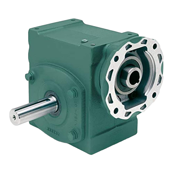
Tigear-2
Instruction Manual
DETACHABLE BASE (QTY.1)
FLAT WASHER (QTY.4)
ALL SIZES EXCEPT SIZE 40
HEX HEAD
CAP SCREW (QTY.4)
Tightening
Torque
(ft-lb)
1/4-20
8
1/4-20
8
5/16-18
17
3/8-16
30
3/8-16
30
3/8-16
30
7/16-14
48
7/16-14
48
5/8-11
130
5/8-11
130
Accessory Kit
®
WARNING: All products over 25 kg (55 lbs) are noted on the shipping
package. Proper lifting practices are required for these products.
STRAIGHT BORE BUSHING KIT
Loosen the six set screws in the hollow bore shaft and insert
the keyed bushing and supplied key into the side of the hollow
bore shaft that will be closest to the driven equipment. Line up
the clearance hole in the bushing with the set screw. Insert the
straight bore bushing into the hollow bore shaft on the opposite
side of the reducer and line up the two clearance holes in the
bushing with the set screws. Apply anti-seize compound to the
driven shaft and slide the reducer onto the driven shaft. Hand
tighten one of the set screws and then hand tighten a set screw
in the same position on the opposite side of the reducer. This
will take up the clearance between the shaft and reducer to the
same side and reduce wobble. Continue the alternating hand
tightening until all the set screws have been tightened. After all
the set screws have been hand tightened, use a torque wrench to
tighten the set screws to the values in the chart below. The 10-32
set screw over the key should be tightened to 3 ft-lb.
Reducer
Size
20
23
26
30
35
1
nor are the
®
Tightening
Bolt or Screw Size
1/4-28
1/4-28
1/4-28
5/16-24
5/16-24
Torque
(ft-lb)
8
8
8
15
15
Advertisement

Related Manuals for Dodge Tigear-2


Summary of Contents for Dodge Tigear-2
- Page 1 Inspections should be made as necessary to assure safe operation under prevailing conditions. Proper guards and other suitable safety devices or procedures as may be desirable or as may be specified in safety codes should be provided, and are neither provided by Dodge nor are the ®...
- Page 2 BOLT-ON BASE (NOT PART OF KIT) RISER BLOCKS (SEE TEXT FOR QTY.) OUTPUT FLANGE (QTY. 1) NOTE: FLAT WASHERS TO BE SOCKET HEAD CAP SCREW USED WITH ALL TIGEAR-2 (QTY. 4) SIZES EXCEPT SIZE 40. Tightening Reducer Bolt or Screw Size Torque Size...
- Page 3 OUTPUT BRACKET KIT OUTPUT SAFETY COVERS Attach the output bracket to the reducer bottom using the INSTALLATION ON BEARING COVER SIDE (applies to supplied screws and lock washers. If a spacer is supplied, install hollow shaft units only): Remove and discard the four retaining the spacer between the reducer top and output bracket and use screws and lock washers on the outside corners of the bearing the longer two bolts supplied.
- Page 4 TRANSITION KIT J-MOUNT BASE KIT Position the transition base on the reducer with the counter Install the J-mount brackets on the reducer. Insert and hand bored holes facing away from the reducer. Insert the supplied tighten the supplied screws and lock washers. Install the reducer socket head screws and lock washers and tighten the screws to in the application and insert and hand tighten the foundation the tightening torque values listed in the below table.
- Page 5 PLUG-IN SHAFT KIT TIE ROD KIT Install a snap ring on the plug-in shaft near the shaft extension Assemble tie rod assembly components—right-hand threaded end. Insert the bore key into the key seat in the plug-in shaft. rod end, right-hand nut, turn buckle, left-hand threaded rod end Remove the two keyway set screws and loosen the remaining and left-hand nut.
- Page 6 Torque all ft-lb) set screws per Table 2 below. Install access hole plug. NOTE: The Tigear-2 three piece couplings are sourced from Table 3–Motor Mounting Bolt Torque two manufacturers. Tigear-2 reducers may contain either manufacturer’s coupling.
- Page 7 ID. Slide Install the torque arm or other mounting bracket to keep the the Tigear-2 reducer onto the shaft until the inner torque arm reducer from rotating about the driven shaft. bushing touches the customer’s structure. The frame must completely support/back up the 1.88”...
- Page 8 Bolt or Screw Size Size Torque (ft-lb) 5/16-18 5/16-18 3/8-16 3/8-16 7/16-14 7/16-14 Dodge Industrial, Inc. *1661-0222* 1061 Holland Road Simpsonville, SC 29681 +1 864 297 4800 © DODGE INDUSTRIAL, INC. All Rights Reserved. Printed in USA. AN RBC BEARINGS COMPANY MN1661 02/22...
Need help?
Do you have a question about the Tigear-2 and is the answer not in the manual?
Questions and answers