Table of Contents
Advertisement
Quick Links
Operating & Maintaining the
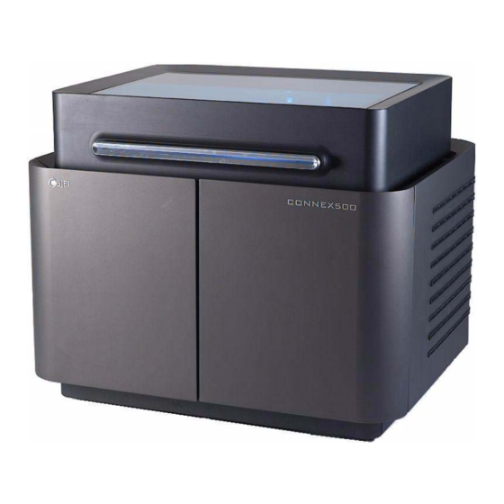
Connex500/350 3-D Printer
Starting the Connex Printer ............................................................... 2
Loading Model and Support Cartridges.......................................... 4
Producing Models ............................................................................... 5
Resuming Production After Printing has Stopped......................... 9
Changing the Model Material ......................................................... 10
Keeping the Connex Printer in Idle Mode..................................... 15
Shutting Down the Connex Printer ................................................ 16
Maintaining the Connex Printer ..................................................... 18
DOC-13000 Rev. E
All manuals and user guides at all-guides.com
Printer Interface Color Key.................................................................. 7
Printing Indicators ................................................................................ 8
Routine Maintenance Schedule......................................................... 18
Cleaning the Print Heads ................................................................... 19
Pattern Test........................................................................................... 21
Improving Print Quality .................................................................... 22
Cleaning and Replacing the Wiper................................................... 23
Replacing the Roller Scraper (Knife) ................................................ 28
Aligning the Print Heads ................................................................... 30
Calibrating Print Heads ..................................................................... 34
Replacing Print Heads........................................................................ 40
Testing and Calibrating the UV Lamps ........................................... 49
Calibrating the Load Cells ................................................................. 51
Replacing the Odor Filter................................................................... 52
Replacing the UV Lamps ................................................................... 52
Built-in Tests......................................................................................... 57
Replacing the Waste Container ......................................................... 62
Cleaning the Exterior Panels ............................................................. 64
7-1
Advertisement
Table of Contents


Need help?
Do you have a question about the Connex500 and is the answer not in the manual?
Questions and answers