Table of Contents
Advertisement
Quick Links
02/13 Rev. 5.08-01
Commissioning & Operation
Unpacking the DPM/PEM ......................... 2
Carrying the DPM/PEM ............................. 3
Checking the contents ............................... 4
Product description ....................................... 5
DPM operating parts ................................. 5
PEM operating parts. ................................ 6
Connections .............................................. 7
Warning notices ........................................ 8
Control panel (display) .............................. 9
Operating modes ..................................... 11
OPERATING INSTRUCTIONS
DPM - PEM
Basic operating procedures .........................13
Connecting the DPM/PEM .......................13
Setting the interface .................................14
Offline operation ......................................15
Online operation ......................................16
Creating a print job ..................................16
Transferring a print job .............................17
Applying memory cards ...........................18
Setting the realtime clock .........................19
Easy Plug .................................................19
The first printer test .....................................20
Settings for the material type ...................20
Printing the status report ..........................20
Advertisement
Table of Contents

Subscribe to Our Youtube Channel
Related Manuals for Novexx Solutions DPM


Summary of Contents for Novexx Solutions DPM
-
Page 1: Table Of Contents
02/13 Rev. 5.08-01 OPERATING INSTRUCTIONS DPM – PEM Commissioning & Operation Preparing the installation of the PEM/DPM ... 2 Basic operating procedures ......13 Unpacking the DPM/PEM ......2 Connecting the DPM/PEM .......13 Carrying the DPM/PEM ......3 Setting the interface .........14 Checking the contents ....... -
Page 2: Preparing The Installation Of The Pem/Dpm
PEM/DPM Only qualified personnel are permitted to install the DPM or PEM! DPM and PEM are in the following also referred to as „the printer“. Unpacking the DPM/PEM 1. Open the box from the top. ... -
Page 3: Carrying The Dpm/Pem
5. Set the printer down in the position [4] shown. Set the printer down in its usual operating position. Carrying the DPM/PEM Hold the DPM/PEM by the rear hood whenever possible. Never think of holding the printer by the front hood [3A] or by the printhead [3B]! Hold the printer whenever possible by the rear hood (A) –... -
Page 4: Checking The Contents
Commissioning & Operation DPM – PEM Checking the contents Before using the DPM or PEM for the first time, take a few minutes to check the following: Check that the printer has not been damaged in transit. If the packaging has been dented or torn, check the contents particularly carefully for shipping damage. -
Page 5: Product Description
Assembly of the pivot unit ply without opening the front for the applicators LTSI, cover. LTP or LTPV. Printhead Exterior of the DPM. Insert diagram Shows the path of the labelling material and ribbon. Ribbon rewinding mandrel Holds the ribbon core onto which used ribbon is wound. -
Page 6: Pem Operating Parts
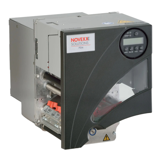
02/13 Rev. 5.08-01 OPERATING INSTRUCTIONS Commissioning & Operation DPM – PEM PEM operating parts. Front hood Cutout for applicator con- Open up to insert ribbon nection To operate an applicator, a D-Sub port is substituted for the cover plate. Control panel LCD display;... -
Page 7: Connections
Notes on how to use the network connection can be found in Special Applications . Rear and bottom of the DPM/PEM with a USI board (optional) incorporated. A Card slot ? For SD/MMC cards ? Is not yet supported B Card slot For CompactFlash cards;... -
Page 8: Warning Notices
Pinch point. Keep hands clear of rollers. A5346 Warning notice on the DPM/PEM The label depicted at [3] warns against the danger of being caught in the mo- ving parts of printer. Warning labels must be replaced if they are lost or become illegible (part nr. -
Page 9: Control Panel (Display)
02/13 Rev. 5.08-01 OPERATING INSTRUCTIONS Commissioning & Operation DPM – PEM Control panel (display) Power indicator Error indicator On-off switch Display Prog button Feed button Online button Apply button DPM/PEM control panel. Power indicator Lights up green, when the printer is switched on. - Page 10 – topic section Info-Printouts and Parameters Remote operation DPM Gen. 3 (or higher) and PEM machines can be equipped with a remote panel operation panel. For this, the machine must provide the appropriate - optional - connector, see chapter Connections / on page 7.
-
Page 11: Operating Modes
02/13 Rev. 5.08-01 OPERATING INSTRUCTIONS Commissioning & Operation DPM – PEM Operating modes Offline mode Printersettings can be made when the device is offline. The offline mode is normally active when the printer is switched on. Print jobs are received via the selected interface but not processed. - Page 12 02/13 Rev. 5.08-01 OPERATING INSTRUCTIONS Commissioning & Operation DPM – PEM Standalone In standalone mode, print jobs are not transferred but saved on a CF card. mode They are started directly from the printer’s control panel or via a connected keyboard.
-
Page 13: Basic Operating Procedures
3. Using the data cable supplied, connect the Centronics interface [6A] on the device to the host computer. Sockets for the Centronics cable (A) and power cable (B) on the DPM/PEM. 4. Turn on the device using the power switch (set to position “1”). -
Page 14: Setting The Interface
Setting the interface According to the factory settings, the DPM/PEM is set for data transfer via Centronics interface. Print data can also be transferred via the serial inter- face, USB or Ethernet interface. -
Page 15: Offline Operation
02/13 Rev. 5.08-01 OPERATING INSTRUCTIONS Commissioning & Operation DPM – PEM Offline operation • Switching from offline mode to online mode: OFFLINE x JOBS ONLINE x JOBS APPLY ONLINE FEED PROG • Switch to online mode when the print job is stopped:... -
Page 16: Online Operation
PROG Creating a print job Essentially, there are two ways of creating a print job: Either by using the DPM/PEM driver for Windows or by creating a text file with print commands. • Windows printer DPM/PEM printer drivers are available for different versions of Windows. You driver can print from nearly every Windows application using the printer drivers. -
Page 17: Transferring A Print Job
02/13 Rev. 5.08-01 OPERATING INSTRUCTIONS Commissioning & Operation DPM – PEM programming knowledge. Furthermore, you will not be able to preview the resulting printout on the screen. Instead, you have to run a test print to see a copy of the finished result. -
Page 18: Applying Memory Cards
A detailed description of how to transfer print jobs via CF cards can be found Special Applications , “Standalone Mode”. Applying memory cards DPM/PEM print modules support the following memory card types: • CompactFlash (CF) Typ I [7] • SD [8] •... -
Page 19: Setting The Realtime Clock
Setting the realtime clock The realtime clock is optional. The DPM/PEM realtime clock can be used, for example, to calculate and print the expiry date of a perishable product. This is how you set the realtime clock: 1. Navigate to the SYSTEM PARAMETER >... -
Page 20: The First Printer Test
02/13 Rev. 5.08-01 OPERATING INSTRUCTIONS Commissioning & Operation DPM – PEM The first printer test Settings for the material type The parameter settings described below provide the printer with the necessa- ry information about the label material used. When printing from a layout pro- gram, these settings are usually provided automatically by the printer driver. - Page 21 02/13 Rev. 5.08-01 OPERATING INSTRUCTIONS Commissioning & Operation DPM – PEM 1. Press the Esc button while in online mode. Display: Print contrast 2. By pressing the Apply / Feed buttons, you can increase or decrease the heat energy of the printhead (in %).
Need help?
Do you have a question about the DPM and is the answer not in the manual?
Questions and answers