Table of Contents
Advertisement
Quick Links
Advertisement
Table of Contents

Related Manuals for Motor Power Company DMR 50-5


Summary of Contents for Motor Power Company DMR 50-5
- Page 1 Installation Guide DMR 50-5/50 V3.0...
- Page 2 DMR 50-5/50 Installation Guide V3.0 Pag. 2 1 Index Product Presentation ........................4 General Description ....................... 4 Safety Information ........................5 Warnings ..........................6 Cautions ..........................7 Directives and Standards ......................8 CE Mark Conformance ......................8 Warranty Information ......................8 Drawings ..........................
- Page 3 This guide delivered subject to the following conditions and restrictions: This guide contains proprietary information belonging to Motor power Company Srl. Such information is supplied solely for the purpose of assisting users of the DMR 50-5/50 servo drive in its installation and configuration.
-
Page 4: Product Presentation
DMR 50-5/50 Installation Guide V3.0 Pag. 4 2 Product Presentation 2.1 General Description The DMR 50-50/50 is a Motoroller servo drive especially designed for Motor Power Company Gearless motoroller. We have different available versions with different Digital I/O configuration (PNP,NPN) The Device is able to operate one or 2 different devices independently, and is compatible with all the size 46 Gearless Motoroller. -
Page 5: Safety Information
DMR 50-5/50 Installation Guide V3.0 Pag. 5 3 Safety Information In order to achieve the optimum, safe operation of the MDR servo drive, it is imperative that you implement the safety procedures included in this installation guide. This information is provided to protect you and to keep your work area safe when operating the MDR and accompanying equipment. - Page 6 DMR 50-5/50 Installation Guide V3.0 Pag. 6 3.1 Warnings To avoid electric hazards to personnel and electrical contacts, never connect/disconnect the servo drive while the power source is on. Power cables can carry a high voltage, even when the motor is not in motion.
- Page 7 DMR 50-5/50 Installation Guide V3.0 Pag. 7 3.2 Cautions The DMR 50-50/50 servo drive contains hot surfaces and electrically-charged components during operation. The maximum DC power supply connected to the instrument must comply with the parameters outlined in this guide.
-
Page 8: Warranty Information
Low Voltage Directive, 73/23/EEC 3.4 CE Mark Conformance The DMR 50-5/50 servo drive is intended for incorporation in a machine or end product. The actual end product must comply with all safety aspects of the relevant requirements of the European Safety of Machinery Directive 98/37/EC as amended, and with those of the most recent versions of standards EN60204-1 and EN292-2 at the least. -
Page 9: Typical Installation
DMR 50-5/50 Installation Guide V3.0 Pag. 9 3.6 Drawings 3.7 Typical Installation The device is designed to be installed on conveyor side Figure 1:Typical Installation inside side channel To fix the device to the conveyor side 2 x M5 screw are necessary. -
Page 10: Specifications
DMR 50-5/50 Installation Guide V3.0 Pag. 10 3.8 Specifications Description Logic Supply 24 Vdc +/- 5% Minimum Supply Voltage 12 Vdc Nominal Supply Voltage 48 Vdc Maximum Supply Voltage 60 Vdc Nominal Current Peak Current 15 A Output Power 240 W Efficiency @ rated Power >... - Page 11 DMR 50-5/50 Installation Guide V3.0 Pag. 11 3.10 Available Models Part Number Description Note 051700000001 DMR 50-5/50 E C 0 PNP - Available on Request 051700000002 DMR 50-5/50 E C 1 NPN - Available on Request 051700000003 DMR 50-5/50 H C 0...
-
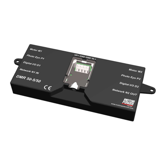
Page 12: Location Of Items
DMR 50-5/50 Installation Guide V3.0 Pag. 12 4 Location of Items To use correctly the device the following items have to be identified: Object Description Power Supply Connector M1,M2 Motor Connector P1,P2 Photo Eye Connector D1,D2 Function Connector N1,N2 Network Connector... - Page 13 DMR 50-5/50 Installation Guide V3.0 Pag. 13 5 Wiring 5.1 Connector XP1 – Power Supply The Connector Type is WAGO 236-404 The recommended power wires are fine-stranded conductor with ferrule plastic collar 0,25-1,5 mm Function Description Power Supply 48Vdc 0 Vdc...
- Page 14 DMR 50-5/50 Installation Guide V3.0 Pag. 14 5.2 Connector M1, M2 – Motor Connector The connector is JST S09B-XASK-1, the mating connector on motor cable is JST XHP-9. Function Description Motor Phase w Motor Phase v Motor Phase u 0 Vdc...
- Page 15 DMR 50-5/50 Installation Guide V3.0 Pag. 15 5.3 Connector P1, P2 - Photo Eye Connector The connector is Phoenix Contact MC 1,5/ 3-G-3,5 – 1844223, the mating connector is Phoenix Contact MC 1,5/ 3-ST-3,5 – 1840379. Function Description Power Supply...
- Page 16 DMR 50-5/50 Installation Guide V3.0 Pag. 16 5.4 Connector D1, D2 - Standard Functions Connector The connector is Phoenix Contact MC 1,5/ 5-G-3,5 – 1844249, the mating connector is Phoenix Contact MC 1,5/ 5-ST-3,5 – 1840395. Function Description Type Enable...
- Page 17 DMR 50-5/50 Installation Guide V3.0 Pag. 17 5.4.1 Digital Input internal wiring +24V D2-2 BAV99S INPUT_RAIL D2-1 BAV99S ENABLE SFH6206-3 EXT-ENABLE 3 ms tau SFH6206-3 EXT-DIR 3 ms tau Typical input current @24Vcd is 7,2 mA 5.4.2 Analog Input internal wiring...
- Page 18 DMR 50-5/50 Installation Guide V3.0 Pag. 18 5.4.3 Digital Output Internal wiring +24V MMBT3906 MMBT3904 25 mA max MMBT3906 PNP_OUT EXT-OUT 100R NPN_OUT MMBT3904 820R The output maximum current have to be < 25 mA. To protect the output is suggested to add an external resistance R >...
- Page 19 DMR 50-5/50 Installation Guide V3.0 Pag. 19 5.5 Connector N1,N2 - Network Connection The Connector is a standard RJ45 Female connector, Mating Connector RJ45 Male, is strongly recommended to use connector with metal case. Function Description Standard RJ-45 cable color...
-
Page 20: Connection Schematic
DMR 50-5/50 Installation Guide V3.0 Pag. 20 6 Connection schematic Warning: Before commissioning, it is essential that the safety instructions in the relevant section are read and understood, and then observed! Non-observance can result in danger to persons or damage to the equipment. - Page 21 DMR 50-5/50 Installation Guide V3.0 Pag. 21 6.1 Schematic circuit for power and logic supply CAUTION: Peak current by switching-on of a variety of series-connected motors. Consequence: Destroying of the integrated electronics possible. ► Using an adequate power supply. Figure 6: Power supply schematic The number of devices you can daisy chain depends on the application, the wire size and the power supply.
- Page 22 DMR 50-5/50 Installation Guide V3.0 Pag. 22 Once the Device is enabled this will follow immediately the V-IN setpoint.
- Page 23 DMR 50-5/50 Installation Guide V3.0 Pag. 23 7.2 DIR – Direction of Rotation The default Direction of rotation is clock wise Motor A Flange if the DIR pin is set to Low. 7.3 V-IN – Speed Variation Speed variation by an external analogue voltage from 0 to 10Vdc.
- Page 24 DMR 50-5/50 Installation Guide V3.0 Pag. 24 7.4 ERR – Error Signal The signal is High when no error is present and Low when we have an error condition. When powering on and off, the error signal could be set. Do not consider this signal during 0.5s to power on, and 2s to power off.
-
Page 25: Led Configuration
DMR 50-5/50 Installation Guide V3.0 Pag. 25 8 LED Configuration On the Device 7 LED are present, not all are used. Here below you can find the position and the functions related to each one. 8.1 LED Map Color Function... - Page 26 DMR 50-5/50 Installation Guide V3.0 Pag. 26 8.2 L1 and L2 Axis Status The LED L1 and L2 show the axis status. STATUS DESCRIPTION Blinking Fast Axis OK and Disabled Solid Green Axis Enabled Axis Fault 8.3 L3 Auxiliary Power Supply Status The LED L3 show the Auxiliary Power Supply Status.
- Page 27 DMR 50-5/50 Installation Guide V3.0 Pag. 27 9 Information on the motor 9.1 Motor Phase Angle For a correct operation, the motor must have a correct electrical configuration. Specification Value Speed 1000 rpm Direction Clockwise (A Motor Flange/Cable Side) Reference Voltage...
- Page 28 DMR 50-5/50 Installation Guide V3.0 Pag. 28 Reference Voltage Hall Signal Value Hall Signal U Hall Signal V Hall Signal W 9.2 Hall signal sequence Hall sensor follow a grey code sequence. Rotating the motor Clockwise (front flange) we must find this configuration.
- Page 29 DMR 50-5/50 Installation Guide V3.0 Pag. 29 9.3 Motor Phase Sequence Rotating clock-wise from motor A flange Figure 7: Motor Direction this is the correct phase sequence Image 1 Where: C1 = Phase U, C2 = Phase V, C3 = Phase W...
- Page 30 Our standard USB to RS485 converter is USB2-H-5001-M that can be found on any major distributor web site, or you can buy form Motor Power Company . Any other converter with same capability can be used. Below the correct dip-switch configuration.
- Page 31 DMR 50-5/50 Installation Guide V3.0 Pag. 31 If you don’t have these wire color, please follow the N1,N2 connection schema. Cable and USB adapter are available at Motor Power Company with the following Part Numbers: 005016000175 : CONVERTITORE INTERFACCIA PC USB/485 USB2-H-5001-M...
- Page 32 DMR 50-5/50 Installation Guide V3.0 Pag. 32 10.2 Standard communication parameters The standard configuration for the Modbus RTU communication is: Data Value Baud Rate 460.800 Data Bit Stop Bit Parity Default Node...
Need help?
Do you have a question about the DMR 50-5 and is the answer not in the manual?
Questions and answers