Advertisement
Quick Links
Quick Installation Guide
IRF-629/IRF-631
1. Overview
The IRF-629 & IRF-631 Converters are used to connect
legacy serial device to ber based Ethernet
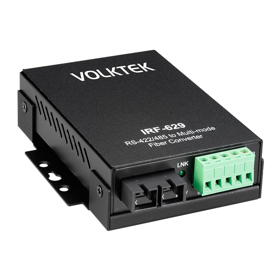
IRF-629 – RS-422/485 to Fiber Converter
IRF-631 – RS-232 to Fiber Converter
2. Package Checklist
Before installing IRF-6xx series, verify that the package
contains the following items:
IRF-629/IRF-631 Converters
Din Rail kit
Power adapter (Check for area type)
IRF-6xx series Quick Installation Guide
IRF-629
LNK
TX
RX
RCV
TX
RS-422/485
Fiber
Fiber
Port
Port
Port
Wallmount
screw hole
DCE
DIP SW
1 2 3 4
ON
1
NA
PWR
2
NA
3
ON:485 2W
OFF:422/485 4W
4
TMR
OFF
DTE
9~32VDC
800mA
DIP
Power
Push
Switches
Input
Button
-1-
3. Hardware Installation Procedure
STEP 1:
Remove the IRF-629/IRF-631 from packing. Connect
the 9-32V DC power adapter to the power input on
rear panel.
STEP 2:
Connect the Fiber port to the networking device. See
the LNK/ACT LED to confirm if the connection is
established.
STEP 3:
Connect the serial port to the serial devices.
STEP 4:
See the DIP switch on rear panel to enable/disable the
required features for appropriate usage.
NOTE: Please use the same hardware version for pair
4. Location
The IRF-629/ IRF-631 can be placed on a desktop or
horizontal surface, wall mounted and Din Rail mounted.
IRF-631
LNK
RX
RCV
RS-232
Port
Wallmount
5. Terminal Block (RS-422/485) Wiring - IRF-629
screw hole
IRF-629 offers 5-pin terminal block port. See the figure
below for the pin assignment.
PWR
RS-422(4W)
9~32VDC
RS-485(4W)
800mA
Power
Input
connection. The version information is shown on
the label, i.e Rev.A.
Wall Mount
Din Rail
RS-485(2W)
(A)Rx+
Tx +
Data +
B
(B)Rx -
Tx -
Data-
A
GND
GND
GND
TX+
Rx +
Rx +
TX -
Rx -
Rx -
-2-
6. DB9 Male Pin Assignment (RS-232)
– IRF-631
IRF-631 o ers 9-pin male console port. See gure be
low for the pin assignment for straight cable. This pin
assignment can also be used for IRF-633/634 as well if
using RS-232 con guration for serial port.
DB9 Male
DB9 Female
DB9 Female
IRF-631
Straight Cable Wiring
DB9
Signal
DB9
2
RD
2
3
TD
3
4
DTR
4
6,1
DSR, DCD
6,1
DSR,DCD
7
RTS
7
8
CTS
8
5
GND
5
9
RI
9
See below for the pin assignment for crossover cable.
DB9 Male
DB9 Female
DB9 Female
IRF-631
Cross Cable Wiring
DB9
Signal
DB9
2
RD
2
3
TD
3
4
DTR
6,1
DSR,DCD
6,1
DSR, DCD
4
7
RTS
7
8
CTS
8
5
GND
5
9
RI
9
-3-
DB9 Male
RS-232
Device
Signal
RD
TD
DTR
RTS
CTS
GND
RI
DB9 Male
RS-232
Device
Signal
TD
RD
DTR
CTS
RTS
GND
RI
Advertisement

Subscribe to Our Youtube Channel
Related Manuals for VOLKTEK IRF-629

Summary of Contents for VOLKTEK IRF-629
- Page 1 IRF-629/IRF-631 Converters Din Rail kit 4. Location Power adapter (Check for area type) The IRF-629/ IRF-631 can be placed on a desktop or IRF-6xx series Quick Installation Guide horizontal surface, wall mounted and Din Rail mounted. Wall Mount Din Rail See below for the pin assignment for crossover cable.
- Page 2 VOLKTEK Corporation warrants this product against defect in materials and workmanship for a period of TWO(2) YEARS to the original purchaser. If you discover a defect, VOLKTEK will, at its sole option, repair or replace the product at no additional charge, provided that you contact...
Need help?
Do you have a question about the IRF-629 and is the answer not in the manual?
Questions and answers