
Related Manuals for EDECOA DPM10


Summary of Contents for EDECOA DPM10
- Page 1 USER MANUAL Model: DPM10 DPM12 DPM15 DPM20 DPM25 DPM30 DPM35 Language: English COPYRIGHT©EDECOA, ALL RIGHT RESERVED, PI-EU-Rev 2.6----English 1 / 14...
-
Page 2: Table Of Contents
13.How to connect two or more batteries?............................11 14.Wiring diagram...................................11 15.Protection features..................................11 16.Service environment................................... 12 17.Problem Causes..................................12 18.Improper use of power inverter..............................13 19.Disposal...................................... 13 20.Warranty..................................... 13 21.Disclaimer of Warranties................................14 22.Compensation..................................... 14 COPYRIGHT©EDECOA, ALL RIGHT RESERVED, PI-EU-Rev 2.6----English 2 / 14... -
Page 3: What Is The Power Inverter
2) One pair of screw cap (Red and Black) 3) One pair of DC input terminal ring (For backup) 4) User manual ×1 5) Ground Cable×1 (Partial model) 6) Battery cable COPYRIGHT©EDECOA, ALL RIGHT RESERVED, PI-EU-Rev 2.6----English 3 / 14... -
Page 4: Installation Environment Requirements
Install it vertically or tilt it back up to 15 ° to allow the fan to cool the machine. Figure 3-1Proper installation Figure 3-2 Installation Space (Unit: mm) Installation space requirements It is recommended that the inverter be mounted at an adequate height for easy operation and subsequent maintenance. COPYRIGHT©EDECOA, ALL RIGHT RESERVED, PI-EU-Rev 2.6----English 4 / 14... -
Page 5: Opening The Device
6. ABOUT THE REMOTE CONTROLLER Tips: The switch of the remote control and the switch of the inverter is parallel. COPYRIGHT©EDECOA, ALL RIGHT RESERVED, PI-EU-Rev 2.6----English 5 / 14... - Page 6 0.1V. If you use very long remote cable, please note that the battery power indicator light maybe not correct. Note: If the remote controller can’t work properly, please try to replace the remote cable first. ET-RC remote controller 1. ON/OFF switch (press 3s),Backlight switch(press once) 2. LCD display COPYRIGHT©EDECOA, ALL RIGHT RESERVED, PI-EU-Rev 2.6----English 6 / 14...
-
Page 7: Technical Data:(Modified Sine Wave
8M RJ45 network lines, display, and switching functions are not affected. Note: If the remote controller can’t work properly, please try to replace the remote cable first. 7. TECHNICAL DATA:(MODIFIED SINE WAVE) COPYRIGHT©EDECOA, ALL RIGHT RESERVED, PI-EU-Rev 2.6----English 7 / 14... -
Page 8: How To Select The Proper Inverter You Need
Inverters should be attached directly to the battery. The wire size depends on the distance between the battery and inverter. The following is a reference to the cable size of the battery recommended by the DC12V system inverter. (DC24V system inverter Cable /2) COPYRIGHT©EDECOA, ALL RIGHT RESERVED, PI-EU-Rev 2.6----English 8 / 14... -
Page 9: Types Of Batteries
1 -2m Cable 75mm² 2 – 4m Cable 70mm² 2 – 4m Cable 80mm² >2m Not recommended 11. TYPES OF BATTERIES You can calculate that the storage battery’s use-time by this formula: COPYRIGHT©EDECOA, ALL RIGHT RESERVED, PI-EU-Rev 2.6----English 9 / 14... -
Page 10: Inverter Appearance Description
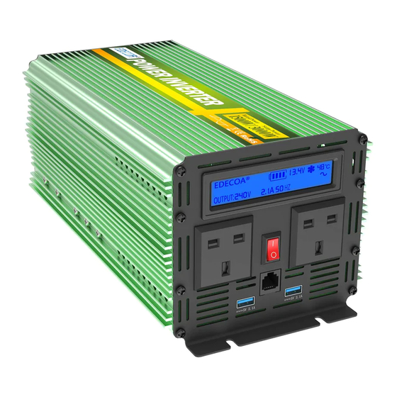
12. INVERTER APPEARANCE DESCRIPTION ① LCD Display ③ Power ON/OFF Switch ② Outlets ④ AC Output : 3P Terminals COPYRIGHT©EDECOA, ALL RIGHT RESERVED, PI-EU-Rev 2.6----English 10 / 14... -
Page 11: How To Connect Two Or More Batteries
24V inverter will destroy the inverter! Reverse polarity protection: when the inverter is connected reversely, inverter’s fuse will blow out to protect the inverter. The DC input side with MOSFET protection will not work. COPYRIGHT©EDECOA, ALL RIGHT RESERVED, PI-EU-Rev 2.6----English 11 / 14... -
Page 12: Service Environment
Make sure that the maximum voltage of the again. inverter: higher than 30V battery controller does not supply voltages higher than 15v(30V) Check that we are not using a panel or wind turbine not regulated for battery charging COPYRIGHT©EDECOA, ALL RIGHT RESERVED, PI-EU-Rev 2.6----English 12 / 14... -
Page 13: Improperuse Of Power Inverter
Do not dispose the product in the household waste. Please dispose it according to the disposal regulations for electronic waste in your country. 20. WARRANTY Warranty for the product is one year starting from the date of purchase. COPYRIGHT©EDECOA, ALL RIGHT RESERVED, PI-EU-Rev 2.6----English 13 / 14... -
Page 14: Disclaimer Of Warranties
Manufacturer:Chang Tian Electrical Technology Co., Ltd Address: HaiXiaDaSha 502 WushigangGongYeQu, DongchengDistrict,DongGuanCity, GuangDong Province,52300,China. Email: info@edecoa.com Designed in Germany, Made in China Visit our official website for more information COPYRIGHT©EDECOA, ALL RIGHT RESERVED, PI-EU-Rev 2.6----English 14 / 14...
Need help?
Do you have a question about the DPM10 and is the answer not in the manual?
Questions and answers
Hello, I have a DPM30 on my lorry. I've not had any issues with it and was using it in the day time but in the night I turned it on and it blew 2 internal fuses. I changed these, wired it back in (correctly) and soon as i turned it on (no load on the inverter to poelwer anything) it blew the 2x 25amp internal fuses again. I've shown in the image which side the fuses are. After I changed the fuses I moved the unit away from anything metal and tried again. As soon as I press the power button it pops the fuses.
The internal fuses on the EDECOA DPM10 inverter could blow when powered on due to:
1. Reverse polarity connection – If the inverter is connected with reversed polarity, the fuse will blow to protect internal components (for models with reverse polarity protection). In models without this protection, internal parts like electrolytic capacitors and MOSFETs may burn out.
2. Input voltage exceeding limits – If the input DC voltage exceeds the allowed range (e.g., above 15.5V for 12V models or above 30V for 24V models), internal components may burn out, causing the fuse to blow.
3. Short circuit or excessive load – Connecting a load that exceeds the inverter's rated power by 120% or has a short circuit can cause the fuse to blow.
To avoid fuse damage, ensure correct polarity, proper voltage range, and avoid overloading or short circuits.
This answer is automatically generated