Table of Contents
Advertisement
Quick Links
Advertisement
Table of Contents

Related Manuals for Titan Attachments FMSS6


Summary of Contents for Titan Attachments FMSS6
- Page 1 SKID STEER FINISH MOWER FMSS6, FMSS5 191539, 191540 Operator’s Manual Read the Operator’s Manual entirely. When you see this symbol, the subsequent instructions and warnings are serious follow without exception. Your life and the lives of others depend on it!
-
Page 2: Important Safety Information
IMPORTANT SAFETY INFORMATION THESE ARE STANDARD PRACTICES THAT MAY NOT APPLY TO THE PRODUCTS DESCRIBED IN THIS MANUAL. SAFETY AT ALL TIMES Thoroughly read and understand the instructions given in this manual before operation. Refer to the “Safety Label” section, read all instructions noted on them. Do not allow anyone to operate this attachment who has not fully read and comprehended this manual and who has not been properly trained in the safe operation of the mower. -
Page 3: For Your Protection
FOR YOUR PROTECTION Thoroughly read and understand the “Safety Label” section, read all instructions noted on them. SHUTDOWN AND STORAGE Lower mower to the ground, remove from the loader. Put loader in park, turn off engine, • and remove the key. Detach and store mower in an area where children normally do not play. -
Page 4: Safety Labels
SAFETY LABELS Your Skid Steer Finish Mower comes equipped with all safety labels in place. They were designed to help you to safety operate your mower. Read and follow their directions. -
Page 5: Section 1: Assembly And Set-Up
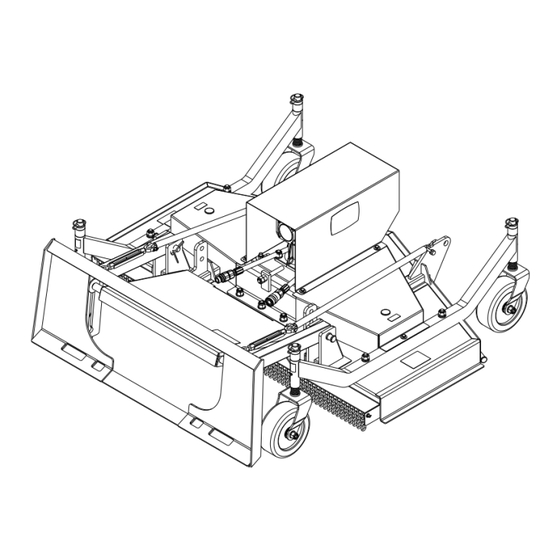
INTRODUCTION APPLICATION The finish mower is designed to cut short grass and lawns and matched the loader. SECTION 1: ASSEMBLY AND SET-UP PACKING DESCRIPTION Remove and check • Remove the packing, check goods without defect and omission • Figure 1-1: Your New Mower as It Is Shipped to You Figure 1-2: The Mower and Accessory in Package... -
Page 6: Packing List
2. PACKING LIST THE DETAILED PACKING LIST OF THE MOWER AND ACCESSORY AS THE FOLLOWING TABLE 1. Table 1-1: Packing List of The Mower and Accessory THE DETAILED DESCRIPTION OF WHEEL BRACKET-ASSEMBLY Figure 1-3: Wheel Bracket Assembly Table 1-2: Wheel Bracket Assembly List... - Page 7 THE DETAILED DESCRIPTION WHEEL FRAME AND FITTNGS Figure 1-4: Wheel Frame and Fittings Table 1-3: Wheel Frame and Fittings List...
-
Page 8: Tool Required
ASSEMBLY The assembly instruction will guide you to finish the final assembly of your new mower easily. 1. TOOL REQUIRED ½” Ratchet wrench with 13mm, 24mm sleeves • 17-19 Spanner. • 2. TORQUE APPLICATION Refer to bolt torque in Section 8 Appendix. 3. -
Page 9: Operation
Step 2: Installing wheel bracket assembly and fittings. Remove the packaging of wheel bracket assembly and fittings. Assemble wheel bracket assemblies on wheel frame as well as spacers. Through the combination of spacers with different height to get the mowing height you need. Parts: 4pcs of wheel bracket assemblies. -
Page 10: Mower Installation
MOWER INSTALLATION NOTE: The illustrations and instructions provided explain how to install a bucket attachment on to a loader. Follow these same instructions if you are installing different attachments such as a grapple, tiller, mower, etc. The attachment mounting frame for the attachment has a top flange that is designed to receive the top edge of the Bob-Tach and the lower part of the frame is designed to receive the Bob-Tach wedges. - Page 11 f. Stop the engine and exit the loader. g. Push down on the Bob-Tach levers until they are fully engaged in the locked position (wedges fully extended through the attachment mounting frame holes). Refer to Figure 1-11. Both levers must contact the frame as shown when locked. Refer to Figure 1-12. WARNING AVOID INJURY OR DEATH The Bob-Tach wedges must extend through the holes in the attachment mounting frame.
-
Page 12: Mower Removal
MOWER REMOVAL NOTE: In muddy conditions or to prevent the attachment from freezing to the ground, put the attachment on planks or blocks before removing the attachment from the loader. a. Lower the lift arms and put the attachment flat on the ground. Lower or close the hydraulic equipment. -
Page 13: Section 2: Daily Inspection
SECTION 2: DAILY INSPECTION ATTACHMENT MOUNT FRAME Inspect the Bob-Tach wedge mounts (item1), mounting flange (item2) and all welds on the attachment mount for wear or damage each time the attachment is removed from the loader. Refer to Figure 2-1. Figure 2-1 MOWER INSPECTION Check the following items every 25 hours of operation:... -
Page 14: Section 3: Operating Instructions
SECTION 3: OPERATING INSTRUCTIONS MOWING PROCEDURE The ground condition and the type of grass being cut will determine the best cutting procedure and ground speed. The mower is designed to cut short grass and lawns. NOTE: When operating the mower, damage to the turf may occur when sharp turns are made. -
Page 15: Lifting The Attachment
NOTE: The chains prevent the mower from scalping the lawn when mowing rough or hilly lawns. h. Engage the auxiliary hydraulics. Note: The auxiliary hydraulics must be activated prior to attachment operation. Increase engine speed to full rpm and drive the loader forward into the work area. Start the blade rotation. -
Page 16: Section 4: Adjustments
SECTION 4: ADJUSTMENTS Belt Adjustment 1. Tool Required ½” Ratchet wrench with 13mm, 19mm sleeves 22-24 Spanner 2. Torque Application Refer to bolt torque in Section 8 Appendix. a. Remove mower from the loader. b. Disconnect item 1 from the mower main body. c. -
Page 17: Cutting Height Adjustment
CUTTING HEIGHT ADJUSTMENT WARNING ATTACHMENT ROLLAWAY CAN CAUSE SERIOUS INJURY OR DEATH. Always park attachment on flat level ground. • Block attachment before removing from machine. • a. Remove mower from the loader. b. Lifting the attachment from the ground to ensure that all wheel brackets can be removed easily after release the safety lock pin. -
Page 18: Section 5: Maintenance And Lubrication
SECTION 5: MAINTENANCE AND LUBRICATION Proper servicing and adjustment are the key to the long life of any farm attachment. With careful and systematic inspection, you can avoid costly maintenance, time, and repair. CLEANING THE MOWER WARNING AVOID INJURY OR DEATH Wear safety glasses to prevent eye injury when any of the following conditions exist: . - Page 19 Always replace all three blades with blades that are equal in weight to prevent vibration. Use only genuine TITAN replacement blades. If any vibration in the mower is felt, the blades must be balanced or replaced. f. Follow step h to i. Refer to Belt Replacement on page20. FIGURE 5-1 BLADE STORAGE At the end of the working season or when the mower will not be used for a long period.
- Page 20 LUBRICATION Lubrication Points Check oil level in gearbox by removing the cap located on top. Oil should be level with middle side of plug hole. Remove top cap and side plug, add oil until it flows from middle side plug hole.
-
Page 21: Section 6: Specification & Capacities
SECTION 6: SPECIFICATION & CAPACITIES... -
Page 22: Section 7: Troubleshooting
SECTION 7: TROUBLESHOOTING... -
Page 23: Section 8: Appendix
SECTION 8: APPENDIX Bolt Torque The tables shown below give correct torque values for various bolts and cap screws. Tighten all bolts to the torques specified unless otherwise noted. Check tightness of bolts periodically, using bolt torque chart as a guide. Replace hardware with the same strength bolt. - Page 24 PARTS DIAGRAM/EXPLODED VIEW FINISH MOWER MAIN BODY PART LIST...
- Page 26 BOB-TACH ASSEMBLY PART LIST...
- Page 27 POWER DRIVE ASSEMBLY PART LIST...
- Page 29 SPINDLE ASSEMBLY PART LIST...
- Page 30 HYDRAULIC SYSTEMS PART LIST...
- Page 32 WHEEL FRAME MOUNT ASSEMBLY PART LIST...
- Page 33 ACKNOWLEDGEMENT OF RISK AND RELEASE OF LIABILITY The use of any equipment, including this one, involves the potential risk of injury. Apart from any warranty claim that might be presented for a claimed defect in material or workmanship of the product, you accept and assume full responsibility for any and all injuries, damages (both economic and non- economic), and losses of any type, which may occur, and you fully and forever release and discharge Titan, its insurers, employees, officers, directors, associates, and agents from any and all claims,...
- Page 34 NEED HELP? CONTACT US FIRST. 1-800-605-7595 info@palletworks.com www.palletforks.com © 2021 Titan Brands...
Need help?
Do you have a question about the FMSS6 and is the answer not in the manual?
Questions and answers