Table of Contents
Advertisement
Quick Links
Advertisement
Table of Contents

Related Manuals for Advance acoustic NOVA 3


Summary of Contents for Advance acoustic NOVA 3
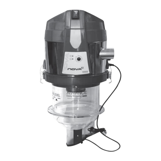
- Page 1 ASSEMBLY, USE AND MAINTENANCE MANUAL INTEGRATED VACUUM UNIT NOVA 3...
- Page 3 INSTRUCTION MANUAL • Type: feeding system for solid fuel boilers • Revision 1.0.4 Vacuum unit integrated vacuum unit INDEX INTRODUCTION 1.1 Use of this manual WARNINGS TECHNICAL DATA, EXPLODED VIEW DRAWINGS AND DIMENSIONS 3.1 Identifi cation plate 3.2 Safety symbols PACKAGING CONTENT PROPER USE OF THE PRODUCT INSTALLATION...
- Page 4 Instruction manual for integrated vacuum unit 1 INTRODUCTION Dear customer, the manufacturer would fi rstly like to thank you for the choice you made in buying an product, whose technical features will certainly meet Your needs. Our products have been designed and manufactured in total compliance with the current regulations, by choosing the best materials to obtain durability and ease of use of the product.
- Page 5 3 TECHNICAL DATA, EXPLODED VIEW DRAWINGS AND DIMENSIONS Model Nova 3 Article AP1000.50.03 English Fuel inlet Ø mm 50 M Discharge pipe Ø mm 50 M IP protection degree Operating temperature min/max °C 0 ÷ 40 Degree of humidity min/max 30 ÷...
- Page 6 Instruction manual for integrated vacuum unit 3.1 Identifi cation plate The CE identifi cation plate is located to the piping network attachment side. Do not remove or damage the label. Vacuum unit type Manufacturer identifi cation ......................CE Mark Model: of conformity IP20...
- Page 7 3.2 Safety symbols DANGER OF VOLTAGE OR ELECTRICAL CURRENT Danger of serious personal injuries. English During maintenance operations, always disconnect the power supply and make sure that it cannot be restored. DANGER OF CUTTING Danger of serious personal injuries. During maintenance operations, always disconnect the power supply and make sure that it cannot be restored.
-
Page 8: Packaging Content
Instruction manual for integrated vacuum unit 4 PACKAGING CONTENT The sales package of the integrated vacuum unit includes the following details: N°1 integrated vacuum unit N°1 installation, use and maintenance manual N°1 warranty form N°1 drilling template N°4 hose clamps N°2 gum sleeves N°4 M5 screw N°4 self-locking nuts M5... -
Page 9: Proper Use Of The Product
5 PROPER USE OF THE PRODUCT The vacuum unit has been designed to be installed for the pneumatic transport of pellets or English other biomass fuels with a medium-fi ne size; it can move a large amount of air into the pipes connected, allowing the solid fuel to be transported together with the air. - Page 10 Instruction manual for integrated vacuum unit 6.1 INSTRUCTIONS FOR INSTALLING THE SYSTEMS Consider that in pneumatic fuel transport systems there are two different types of pipe features: - sections of pipes where only air and eventually dust pass through B- sections of pipes where both air and fuel pass through Mandatory all sections of piping through which the fuel passes must be made with PU or steel pipe and they must be connected to be antistatic.
- Page 11 To facilitate these operations, the vacuum unit is supplied with a template for preparing the holes. See fi gures 1 to 3. Where it is not possible to place the dispenser discharge outlet inside the tank, a maximum level sensor must be installed in the tank, connecting it to the panel which controls the system, to English prevent fuel leaks during the loading cycles.
- Page 12 Instruction manual for integrated vacuum unit 6.3 Connection to the piping network Both the Ø 50 mm pipes of the vacuum unit must be connected with at least one piece of antistatic fl exible hose with equal diameter, secured with well-fi xed hose clamps. The other end of the antistatic pipe should be connected to the rest of the fuel transport system, which can still be made with fl...
- Page 13 Electric cabling legend: English Connection Function Control Input: - Timer MICRO On-off control - Sensor - Boiler control Output: Normally open contact - - fuel extraction system max 1 A activation Example of electrical connections 230 V ac Example: Possible motorized fuel extraction system MICRO ON-OFF...
-
Page 14: Start-Up And Use
Instruction manual for integrated vacuum unit 7 START UP AND USE Before proceeding to unit start up, it is opportune to check that the pipes are correctly and fi rmly fi xed to it, and that electrical connections comply with the current law, as well as the electric system to which it is connected. - Page 15 7.1 Alarm light The control panel of vacuum unit has a red led called “ALARM”: in the case it is illuminated, the unit and consequently the fuel transport system stop. This blockage may be due to English various causes. The most frequent are: A - Lack of fuel in the storage tank.
- Page 16 Instruction manual for integrated vacuum unit 8 MAINTENANCE AND END-OF-LIFE Before carrying out any maintenance operation, it is obligatory to disconnect the power sup- ply cable from the main socket and to aerate the premises in which it is installed for at least 15 minutes.
-
Page 17: Safety Requirements
9 SAFETY REQUIREMENTS FOR FUEL STORAGE TANKS English SAFETY REQUIREMENTS for pellet storage tanks with capacity up to 10 t Keep the doors closed. Access is permitted only to authorized personnel under the supervision of a person outside Do not smoke and approach fl ames or other sources of ignition. -
Page 18: Warranty
Instruction manual for integrated vacuum unit 10 WARRANTY PRODUCT LIMITED WARRANTY CONDITIONS The Manufacturer guarantees to the original purchaser the absence of defects in material and workmanship of the product for the period stated, from the date of purchase. Except as prohibited by applicable law, this warranty is non transferable and it is limited to the original purchaser. - Page 19 11 CERTIFICATION Declaration of absence of harmful substances The manufacturer declares that their products and equipment are made with materials compli- English ant with the current regulations regarding protection of health and the environment and does not contain substances classifi ed as SVHC (Substance of Very High Concern) in accordance with Regulation EC 1907/2006 (REACH, or registration, evaluation, authorization and restric- tion of chemical substances).
- Page 20 F0920507.1 info@advanceeasymoving.com - www.advanceeasymoving.com...
Need help?
Do you have a question about the NOVA 3 and is the answer not in the manual?
Questions and answers