Table of Contents
Advertisement
Quick Links
Addressable Fire Alarm Systems /
Fire Alarm System
Maintenance Guide & Log Book
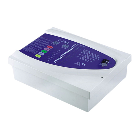
Fire Alarm Panel-F-A16L
1. FIRE ALARM CONTROL PANEL SAFETY ISSUES............................................... 2
How to use this Fire Alarm Panel safely
2. THE PURPOSE OF A FIRE ALARM SYSTEM...................................................... 2
Introduction to fire alarms
What the end users responsibility is, including daily, weekly, quarterly & annual checks
4. PANEL INDICATIONS & CONTROLS ................................................................. 5
A list of indicator LEDs & Control Buttons on the F-A16L Fire Alarm Panel
5. THE FIRE CONDITION ................................................................................. 14
6. THE FAULT CONDITIONS ...............................................................................15
6.2 WHAT TO DO IF A FAULT CONDITION OCCURS
7. DISABLEMENTS ............................................................................................ 15
8. SYSTEM DESCRIPTION ................................................................................... 15
List of system comments
9. FIRE ALARM LOG BOOK.................................................................................17
A place for you to record details of events such as fires, false alarms, callouts, etc.
10. COMMISSIONING THE SYSTEM, INCLUDING P.S.E........................................... 20
CONTENTS
Advertisement
Table of Contents

Related Manuals for Lexing Panel-F-A16L


Summary of Contents for Lexing Panel-F-A16L
-
Page 1: Table Of Contents
Addressable Fire Alarm Systems / Fire Alarm System Maintenance Guide & Log Book Fire Alarm Panel-F-A16L CONTENTS 1. FIRE ALARM CONTROL PANEL SAFETY ISSUES………………………..……………… 2 How to use this Fire Alarm Panel safely 2. THE PURPOSE OF A FIRE ALARM SYSTEM……………………………………………… 2 Introduction to fire alarms 3. -
Page 2: Fire Alarm Control Panel Safety Issues
Addressable Fire Alarm Systems / Fire Alarm System Maintenance Guide & Log Book 1. FIRE ALARM CONTROL PANEL SAFETY ISSUES There is no need to open this fire alarm during normal operation. Any work carried out on this system must be performed by a competent person who is familiar with this type of system. -
Page 3: User Responsibilities & Maintainence Of The Fire Alarm System, Including The Facp & Its Integral Pse
Addressable Fire Alarm Systems / Fire Alarm System Maintenance Guide & Log Book Disablements An engineer may be required to work on part of a system, while the system is still active (e.g. extending a detection zone). During such circumstances, it would be advisable to disable that zone, so that it will not give false alarms. - Page 4 Addressable Fire Alarm Systems / Fire Alarm System Maintenance Guide & Log Book The responsible person must: 1. Check the system at least once every 24 hours to ensure there are no faults present. 2. Ensure there are arrangements for testing and maintaining the system. 3.
-
Page 5: Panel Indications & Controls
Addressable Fire Alarm Systems / Fire Alarm System Maintenance Guide & Log Book Check every detector, call point, sounder and all auxiliary equipment for correct operation. Check Transformer output Voltage (32 VAC), Charger Voltage. Every Five Years (to be carried out by authorised service personnel only) Carry out a complete wiring check in accordance with the testing and inspection requirements of the relevant National wiring regulations. -
Page 6: General Controls
Addressable Fire Alarm Systems / Fire Alarm System Maintenance Guide & Log Book 4.1 GENERAL CONTROLS When the Panel is in its Normal state, the indicator lights on the front of the enclosure give a comprehensive overview of the System’s current status. Any Fire and Fault conditions are clearly displayed, and any disablements highlighted. -
Page 7: Checking The Panels Indication Leds
Addressable Fire Alarm Systems / Fire Alarm System Maintenance Guide & Log Book ALARM CONSTANT RED Some channel detector is alarm CONSTANT GREEN There is a detector in this channels CONSTANT There is no detector in this channels YELLOW CONSTANT This channels of detectors have already alarm, has lost ALARM FLASHING RED... -
Page 8: Fire Alarm System And Its Accessories
Addressable Fire Alarm Systems / Fire Alarm System Maintenance Guide & Log Book 4.5 FIRE ALARM SYSTEM AND ITS ACCESSORIES To strengthen security, besides the standard configure we provide, you can add other fittings. Our fittings for your choice have: Wireless smoke alarm (LX928-V7) /siren(LX-SR)/glass broken call. -
Page 9: Lx928-V7 Smoke Detector Using Instruction
Addressable Fire Alarm Systems / Fire Alarm System Maintenance Guide & Log Book 4.6 LX928-V7 SMOKE DETECTOR USING INSTRUCTION The product is a new type of photoelectric smoke detector, it use matched with F-A16L.When it detects smoke, its LEDs flash quickly and the main F-A16L alarm, dial, which tell you in advance that fire will occurs and avoid unwanted loss, and take you safety and convenience. - Page 10 Addressable Fire Alarm Systems / Fire Alarm System Maintenance Guide & Log Book 10CM(4'') MINIMUM CEILING ANYWGERE IN THIS AREA BEST HERE NEVER HERE ACCEPTABLE HERE 0.9M(3ft) 0.9M(3ft) DIAGRAM 1 HORIZONTAL DISTANCE FROM PEAK SIDE WALL DIAGRAM 2 Where Not Fit To Install Smoke Detector 1.
- Page 11 Addressable Fire Alarm Systems / Fire Alarm System Maintenance Guide & Log Book Connection-wire Diagram Loosen the screws arrow pointing in the right figure and twine the line head on the screw thread under gasket. And then tighten up the screws. •Terminal 5 connect R+ "...
- Page 12 Addressable Fire Alarm Systems / Fire Alarm System Maintenance Guide & Log Book Regular Maintenance 1. Test it at least once a week. 2. Clean the smoke alarm at least once a month. Gently vacuum off dust using vacuum’s soft brush attachment.
-
Page 13: Glass Broken Call Point Installation Instructions
Addressable Fire Alarm Systems / Fire Alarm System Maintenance Guide & Log Book 4.7 GLASS BROKEN CALL POINT INSTALLATION INSTRUCTIONS Function Under emergency condition break the glass and make the main alarm. Electrical Rating AC (50Hz) 8V min. 250V max up to 10A 48V max up to 3A DC 8V min. -
Page 14: The Fire Condition
Addressable Fire Alarm Systems / Fire Alarm System Maintenance Guide & Log Book 5. THE FIRE CONDITION 5.1 HOW THE F-A16L INDICATES AN ALARM When the F-A16L Fire Alarm Panel is set into alarm: LED will show that which zone is alarm. Then the ALARM LED in the alarm panel will light. -
Page 15: The Fault Conditions
Addressable Fire Alarm Systems / Fire Alarm System Maintenance Guide & Log Book If the call point is still active, or the detector is still smoky, this will cause another alarm straight after the panel is reset, so will set off alarm bells again. 6. - Page 16 Addressable Fire Alarm Systems / Fire Alarm System Maintenance Guide & Log Book FIRE ALARM SYSTEM SUMMARY:...
-
Page 17: Fire Alarm Log Book
Addressable Fire Alarm Systems / Fire Alarm System Maintenance Guide & Log Book 9. FIRE ALARM LOG BOOK It is recommended that this LOG BOOK section of the Manual be maintained by the responsible person(s) on site, who should ensure every event is properly recorded (including fire alarm conditions, failures, tests, temporary disconnections, disablements, enablements, dates of installing engineers’... - Page 18 Addressable Fire Alarm Systems / Fire Alarm System Maintenance Guide & Log Book MAINTENANCE WORK ADDITIONAL WORK DATE TIME ZONE / LOCATION REASON FOR WORK WORK CARRIED OUT SIGNED REQUIRED...
- Page 19 Addressable Fire Alarm Systems / Fire Alarm System Maintenance Guide & Log Book FALSE ALARMS DATE TIME ZONE / CAUSE (IF MAINTENANCE MAINTENANCE CATEGORY FURTHER SIGNED LOCATION KNOWN) OR VISIT NEEDED FINDINGS OF FALSE ACTION ACTIVITIES IN (YES/NO) ALARM REQUIRED ALARM AREA...
-
Page 20: Commissioning The System, Including P.s.e
• The Certificate of Installation & Commissioning should be completed, and the whole user manual passed to the relevant person on site. NINGBO LEXING INDUCTOR ELECTRONIC CO.,LTD Add:No.35 Zhuquan Road,Science&Technology Area. E-mail:lexing@lexing.com.cn Ninghai,Ningbo,Zhejiang,China E-mail:lexing@globalmarket.com...
Need help?
Do you have a question about the Panel-F-A16L and is the answer not in the manual?
Questions and answers