
Subscribe to Our Youtube Channel
Related Manuals for Luminex LumiNode 4DIN


Summary of Contents for Luminex LumiNode 4DIN
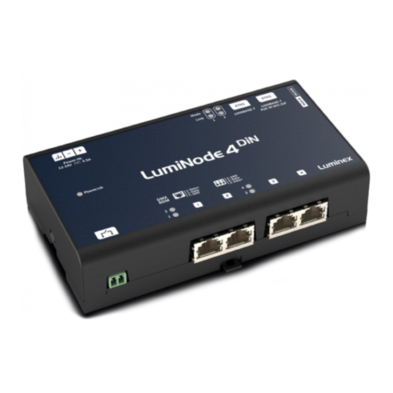
- Page 1 Description: User Manual LumiNode 4DIN. REVISION: 20220629-REV 2.4.1 USER MANUAL LUMINODE PRODUCT FAMILY LumiNode 4DIN THANKS FOR CHOOSING LUMINEX...
-
Page 2: General Information
IMPORTANT NOTICE: DO NOT MODIFY THIS UNIT! This product, when installed as indicated in the instructions contained in this manual, meets FCC requirements. Modifications not expressly approved by Luminex Lighting Control Equipment nv may void your authority, granted by the FCC, to use the product. -
Page 3: Warranty Information
Returning under warranty Any product unit or parts returned to Luminex LCE must be packaged in a suitable manner to ensure the protection of such product unit or parts, and such package shall be clearly and prominently marked to indicate that the package contains returned product units or parts. -
Page 4: Table Of Contents
Table of Contents GENERAL INFORMATION ......2 WARRANTY INFORMATION ......3 1. - Page 5 table of Contents Toolbox page ....... . 20 Profile manager ....... 20 Firmware .
-
Page 6: Applications
1. Applications 1. Applications A few examples of applications where the LumiNode4 can be used: ƒ Touring & Live events ƒ Studio’s ƒ Cruise ships/Yachts ƒ Theatres ƒ Arena/Stadium lighting ƒ Architainment lighting ƒ Theme parks ƒ Campuses ƒ Houses of Worship ƒ... -
Page 7: Installation
2. Installation 2. Installation 2.1 mounting the device LumiNode 4 is designed to be mounted directly onto a standard DIN (IEC/EN 60715) rail. Before fitting the device, please make a note of the IP address as this is located at the bottom of the device. The device clips onto the rail. -
Page 8: Connection To The Network
2 | InstallatIon Alternatively, the LumiNode series are 802.3af compliant (PoE), so that each LumiNode will act as a PD (Powered Device) and can be powered by any compliant PSE (Power Sourcing Equipment) such as Ethernet switch, midspan and PoE injector. All models can only be powered with PoE via ETH2! 2.3 Connection to the network To get the LumiNode 4 online in your system, connect either port ETH1 or ETH2 to a computer, or to a... -
Page 9: Connection To The Web Interface
LumiNet Monitor is available for Windows and MacOS and can be found in the download section of our website: http://www.luminex.be/support-2/product-downloads/ How to reset your LumiNode through LumiNet Monitor: ƒ With a computer connected to the device, open LumiNet Monitor (version 2.3.3 or above). -
Page 10: Configuration
Launch your favourite web browser and type the IP address of your LumiNode. Press enter to validate. 3.1 Node Page (A) Identify: Clicking on the Luminex logo will identify your LumiNode in the network. The Mode LED will flash green for 5 seconds. In the web-UI you get the text “Identified” under the logo. -
Page 11: How To Reset A Process Engine
3 | ConfIGuratIon HOW TO RESET A PROCESS ENGINE To reset a process engine, follow the following steps: ƒ Hover your mouse over the top left corner of the process engine and select the tick box. ƒ Click on the trash can icon at the top right corner above the first process engine. A blank process engine appears as follows: If you want to reset all the process engines at once, navigate to the top left above the first process engine and select the tick box “Select all Process Engines”... -
Page 12: How To Copy A Process Engine
3 | ConfIGuratIon HOW TO COPY A PROCESS ENGINE Once you have created your first process engine, select it by clicking on the tick box in the top left corner. A handle appears at the bottom centre of the process engine. Click and drag the handle down, to select other process engines. -
Page 13: Dmx Settings
3 | ConfIGuratIon DMX SETTINGS On the DMX/RDM page, at the bottom of the page, you find the DMX settings. ƒ DMX Framerate in Frames Per Second. ƒ Breaktime in microseconds. ƒ DMX output time continuous by default is enabled and the LumiNode will keep outputting the last received stream packages on the DMX. -
Page 14: Play Page
3 | ConfIGuratIon 3.3 Play page The play page is devided in two sub menus: SHOW Here you select in which show you want to record cues, which cue number and the fade time in seconds. Other options here are: ƒ... -
Page 15: Global Settings
3 | ConfIGuratIon 3.4 Global settings The global settings page is divided in five sub menus: CONTROL SOURCE Here, you can set the type of protocol, the universe number, and the controller IP address for each control source. If the IP address 0.0.0.0 is used all devices in the network generating the assigned control protocol and universe can be the control source. -
Page 16: Miscellaneous
3 | ConfIGuratIon x 24 - 31: Input 3 x 32 - 39: Input 4 ƒ Play x 8 - 15: Go x 16 - 23: Forward x 24 - 31: Back x 32 - 39: Reset x 101 - 140: Record ƒ... -
Page 17: Network
3 | ConfIGuratIon 3.5 network The network page is devided in two scenarios. SCENARIO 1(A): (DEFAULT) The Lighting data input/output and the management of the LumiNode are all assigned to the same network group and share a single IP address. In the IP address section (C): ƒ... - Page 18 3 | ConfIGuratIon In the Input/Output interface: ƒ Enter the IP address you wish to use (C). ƒ Enter the subnet you wish to use. ƒ Enter a gateway IP address if required. ƒ Enable/Disable Allow config (D). When disabled, users will not be able to reach the web-UI on this IP address.
-
Page 19: Group/Vlan Advanced Settings
3 | ConfIGuratIon GROUP/VLAN ADVANCED SETTINGS To change the settings for a group, click on the Edit group option in the Group/Trunks section. With a group selected you can: ƒ Change the VLAN ID. ƒ Change the name for ease of identification. ADD OR EDIT A TRUNK To Add or Edit a Trunk, click the Edit Trunk option in the top right of the Group/Trunks section. -
Page 20: Toolbox Page
You can upgrade the LumiNode with our latest firmware. To upgrade the unit, please apply the following procedure: ƒ Download the latest firmware from the support section of our web site, https://www.luminex.be/ support-2/product-downloads/ ƒ Extract the downloaded archive and have a look at the release notes included. -
Page 21: Reset
3 | ConfIGuratIon ƒ Select the file you have extracted. ƒ The LumiNode will start the firmware upgrade. The unit will reboot after the upgrade is completed. RESET In this panel, you can reset the LumiNode, with two separate options: ƒ... -
Page 22: Web Api
4. Web API 4. Web API The LumiNode range supports the use of Web API. For a detailed list of available actions via Web API, please type the following in your favourite web browser: http://IP_OF_YOUR_DEVICE/api/doc... -
Page 23: Luminode In Detail
The LumiNode series is a new range of network converter, inheriting more than a decade of experience from the Luminex Ethernet-DMX converter design and manufactoring. In the past, most of the people were designing their system according to the number of universes and DMX ports they would need on their lighting control system. -
Page 24: Input
5 | lumInoDe In DetaIl INPUT A process engine supports the following inputs: DMX: A DMX source, such as a lighting control desk, can be connected to any of the DMX port(s) of the LumiNode. You will need to use a male to male adaptor to connect the console to the DMX port of the LumiNode. In the input configuration, you click on the port you wish to use as an input port, to enable the DMX input. - Page 25 5 | lumInoDe In DetaIl The following rules apply: x If all sources have the same priority HTP will be applied. x If for a source the 0xDD packet is not available, the standard universe priority is being used. x The number of sources is unlimited. ƒ...
- Page 26 5 | lumInoDe In DetaIl RTTrPL: The LumiNode process engine supports Real Time Tracking Protocol for Light, by Cast Software. As an example, the LumiNode can be used to transition between a lighting console and a BlackTraX tracking system, seamlessly. Tick the box to select RTTrPL as an input protocol.
-
Page 27: Output
5 | lumInoDe In DetaIl Select the control channel you want to use to control the cue list. Use the cog wheel to set the source protocol and universe and if required a specific controller IP. Control channel options: 8 - 15: Go, play the next cue in the cue list. 16 - 23: Forward, pre-set the next cue. -
Page 28: Mode Definition
5 | lumInoDe In DetaIl KiNET: All data handled by the process engine can be sent back to the network as a new or the same KiNET universe. Here you can set the version you wish to use, the universe number you wish to use (default is Don’t care), the priority (default 0) and the port number you wish to send this universe to. - Page 29 5 | lumInoDe In DetaIl Auto Recover: ƒ When auto recovery is enabled the LumiNode will switch back to input one as soon as this is back available in the network. In this case the warning for the missing backup control source can be ignored. ƒ...
- Page 30 5 | lumInoDe In DetaIl Control channel mapping: 000 - 007 Do Nothing/Idle (current active source stays active) 008 - 015 Input 1 016 - 023 Input 2 024 - 031 Input 3 032 - 039 Input 4 040 - 247 Future use 248 - 255 Do Nothing/Idle (current active source stays active)
-
Page 31: Patch Option
5 | lumInoDe In DetaIl PATCH OPTION Depending on the selected mode you applied to your process engine, you will be able to modify the patch for your sources. Once in the process engine panel, click on the patch icon to open the patch panel. From there, you can apply the patch you wish per channel. -
Page 32: Master/Limit Explained
5 | lumInoDe In DetaIl Press Apply to save your settings. MASTER/LIMIT EXPLAINED: Master: When choosing the Master option, we configure a control channel to act like a grand master. The output is scaled to each individual channel. (Master value x Channel value / 255) For example: Channel 1 = 200 Channel 2 = 229... -
Page 33: Technical Support
If you need to ask our team for more help or you need to return a device to Luminex for diagnostics or repair, you can also fi nd the option on this page to request an RMA or start a support ticket. -
Page 34: Credits
7. Credits 7. Credits The following credits are available for this manual: ƒ Art-Net™ Designed by and Copyright Artistic Licence Holdings Ltd. ƒ ANSI E1.20 - 2010 Entertainment Technology RDM, Remote Device Management over DMX512 Networks. ƒ ANSI E1.31 - 2018 Entertainment Technology - Lightweight streaming protocol for transport of DMX512 using ACN. -
Page 35: Technical Specifications
8. Technical Specifications 8. Technical Specifications CONNECTIVITY DMX/RDM 4x RJ45-DMX Network 2x gigabit RJ45 Contact Closure 1x 2-pin plugable terminal block 1x 3-pin plugable terminal block Power PoE-802.3af (Class 0) DMX FEATURES DMX512 (1986 & 1990) Supported protocols DMX512-A RDM ANSI E1.20-2010 DMX port direction Input or output (configurable) DMX port isolation... - Page 36 8 | teCHnICal sPeCIfICatIons MANAGEMENT Built in Web server Configuration Documented Web API ENVIRONMENTAL Operating temperature -10 to +60°C Storage temperature -10 to +70°C Humidity (non condensing) 5 to 95% RH MECHANICAL Enclosure Robust plastic housing Dimensions (W x D x H) 156.3 x 86 x 35.8mm Weight 0.27kg...
-
Page 37: Rj45 Pin-Out
8 | teCHnICal sPeCIfICatIons RJ45 PIN-OUT For the LumiNode4DIN equipped with RJ45 ports we are using the following connection schedule from the ANSI E1-11 DMX Standard: Table 4 Connection Schedule for DMX512 Equipment Using IEC 60603-7-8 Position Modular Connectors: Pin (Wire) Wire Colour DMX512 Function White/Orange... -
Page 38: Disclamer
8 | teCHnICal sPeCIfICatIons DISCLAMER Luminex LCE operates a policy of continuous development. Luminex LCE reserves the right to make changes and improvements to any of the products described in this document above without prior notice. Specifications are subject to change without notice. - Page 39 YOUR NETWORK SOLUTION FOR AUDIO, VIDEO AND LIGHTING EFFECTIVE, RELIABLE, ACCESSIBLE...
- Page 40 Slamstraat 13 | 3600 Genk | Belgium | T +32 11 812 189 | info@luminex.be | www.luminex.be...
Need help?
Do you have a question about the LumiNode 4DIN and is the answer not in the manual?
Questions and answers