Table of Contents
Advertisement
Quick Links
CAN-CBX-AIR/2
Wireless CAN-Bridge
with USB Interface
Hardware Manual
to Product C.3051.02, C.3051.04
CAN-CBX-AIR/2
Hardware Manual • Doc. No.: C.3051.21 / Rev. 1.0
Page 1 of 53
esd electronic system design gmbh
Vahrenwalder Str. 207 • 30165 Hannover • Germany
http://www.esd.eu
Phone: +49 (0) 511 3 72 98-0 • Fax: +49 (0) 511 3 72 98-68
Advertisement
Table of Contents

Subscribe to Our Youtube Channel
Related Manuals for ESD CAN-CBX-AIR/2


Summary of Contents for ESD CAN-CBX-AIR/2
- Page 1 CAN-CBX-AIR/2 Hardware Manual • Doc. No.: C.3051.21 / Rev. 1.0 Page 1 of 53 esd electronic system design gmbh Vahrenwalder Str. 207 • 30165 Hannover • Germany http://www.esd.eu Phone: +49 (0) 511 3 72 98-0 • Fax: +49 (0) 511 3 72 98-68...
- Page 2 The information in this document has been carefully checked and is believed to be entirely reliable. esd makes no warranty of any kind with regard to the material in this document, and assumes no responsibility for any errors that may appear in this document. In particular descriptions and technical data specified in this document may not be constituted to be guaranteed product features in any legal sense.
- Page 3 Revision Chapter Changes versus previous version Date First English Version 2013-05-30 Technical details are subject to change without further notice. CAN-CBX-AIR/2 Hardware Manual • Doc. No.: C.3051.21 / Rev. 1.0 Page 3 of 53...
- Page 4 ● Do not operate the CAN-CBX-AIR/2 adjacent to heat sources and do not expose it to unnecessary thermal radiation. Ensure an ambient temperature as specified in the technical data. ● Do not use damaged or defective cables to connect the CAN-CBX-AIR/2 and follow the CAN wiring hints in chapter: "Correctly Wiring Electrically Isolated CAN Networks".
-
Page 5: Table Of Contents
Table of contents 1. Overview............................7 Scope of Delivery........................8 1.1.1 CAN-CBX-AIR/2 ......................8 1.1.2 CAN-CBX-AIR/2-Bridge....................8 Connecting Diagram........................9 3. LEDs............................10 Position of the LEDS......................10 Indication........................10 3.2.1 Indicator States......................10 3.2.2 Operation of the Error LED..................11 3.2.3 Operation of the Status LED ..................11... - Page 6 Grounding......................49 11.3 Short Circuit in CAN Wiring....................49 11.4 CAN_H/CAN_L-Voltage ....................49 11.5 CAN Transceiver Resistance Test ..................50 Software Licenses........................51 Declaration of Conformity......................52 Order Information........................53 Page 6 of 53 Hardware Manual • Doc. No.: C.3051.21 / Rev. 1.0 CAN-CBX-AIR/2...
-
Page 7: Overview
LEDs Figure 1: Block circuit diagram The CAN-CBX-AIR/2 is designed for wireless bridging two different CAN networks via a radio link. It supports data exchange between CAN nets with two different baud rates. This stand-alone mode can be used e.g. to get access to CAN modules installed at turning machine parts via a point-to- point connection (see example1, page 24). -
Page 8: Scope Of Delivery
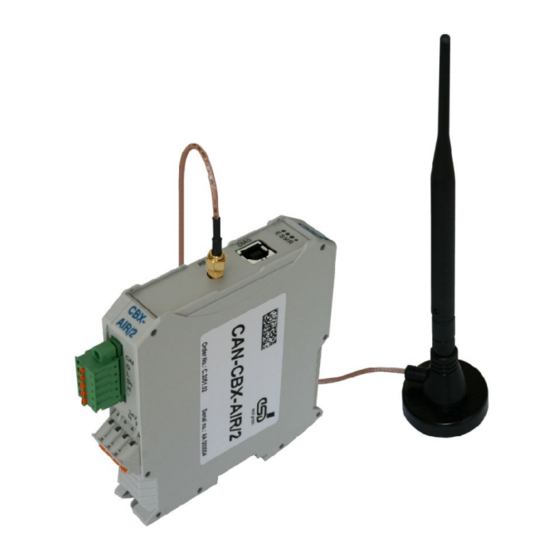
Overview 1.1 Scope of Delivery 1.1.1 CAN-CBX-AIR/2 The following articles are included in delivery of CAN-CBX-AIR/2 (esd order no.: C.2051.02): - 1x CAN-CBX-AIR/2 module - 24V power supply connector - CAN line connector - 2,4 GHz antenna with antenna cable - USB cable (1m) 1.1.2 CAN-CBX-AIR/2-Bridge... -
Page 9: Connecting Diagram
Connecting Diagram 2. Connecting Diagram Figure 2: Connecting diagram of CAN-CBX-AIR/2 See also page 37 et. seqq. for signal assignment of the connectors. Please pay attention to the connection conditions of the individual interfaces. CAN-CBX-AIR/2 Hardware Manual • Doc. No.: C.3051.21 / Rev. 1.0... -
Page 10: Leds
LED 200 ms on, 1000 ms off 2 flashes LED 200 ms on, 200 ms off, 200 ms on, 1000 ms off Table 1: Indicator states Page 10 of 53 Hardware Manual • Doc. No.: C.3051.21 / Rev. 1.0 CAN-CBX-AIR/2... -
Page 11: Operation Of The Error Led
RF transmitter is transmitting a data packet Table 5: Description of RF-Status LED Note: As the module constantly switches between RX and TX, the RF-Status LED is usually noticed as "flickering". CAN-CBX-AIR/2 Hardware Manual • Doc. No.: C.3051.21 / Rev. 1.0 Page 11 of 53... -
Page 12: Hardware Configuration
At the moment the address is set to 00. The module acts as transparent bridge (no CANopen), configurable by the configuration tool. The CANopen mode will be available with firmware update. Page 12 of 53 Hardware Manual • Doc. No.: C.3051.21 / Rev. 1.0 CAN-CBX-AIR/2... -
Page 13: Setting The Baud Rate
Setting Baud rate [Hex] [Kbits/s] 1000 666.6 333.3 66.6 33.3 12.5 baud rate set by configuration tool Table 6: Index of the baud rate CAN-CBX-AIR/2 Hardware Manual • Doc. No.: C.3051.21 / Rev. 1.0 Page 13 of 53... -
Page 14: Hardware Installation
Do not remove the antenna during operation! Please note that the CAN bus has to be terminated at both ends! esd offers special T-connectors and termination connectors. Additionally the CAN_GND signal has to be connected to earth at exactly one point in the CAN network. -
Page 15: Using Inrailbus
CAN-CBX modules. Place the CAN-CBX module with the DIN rail guideway on the top edge of the mounting rail. Figure 6: Mounting CAN-CBX modules CAN-CBX-AIR/2 Hardware Manual • Doc. No.: C.3051.21 / Rev. 1.0 Page 15 of 53... -
Page 16: Connecting Power Supply And Can Signals To Cbx-Inrailbus
Plug the terminal plug into the socket on the right of the mounting-rail bus connector of the InRailBus, as described in Figure 5. Then connect the CAN interface and the power supply voltage via the terminal plug. Page 16 of 53 Hardware Manual • Doc. No.: C.3051.21 / Rev. 1.0 CAN-CBX-AIR/2... -
Page 17: Connection Of The Power Supply Voltage
CBX station. The signals are then connected through the CAN-CBX station via the InRailBus. To lead through the CAN signals the CAN bus connector of the last CAN-CBX module of the CAN- CAN-CBX-AIR/2 Hardware Manual • Doc. No.: C.3051.21 / Rev. 1.0... -
Page 18: Remove The Can-Cbx Module From Inrailbus
Note: It is possible to remove individual devices from the whole without interrupting the InRailBus connection, because the contact chain will not be interrupted. Page 18 of 53 Hardware Manual • Doc. No.: C.3051.21 / Rev. 1.0 CAN-CBX-AIR/2... -
Page 19: Software Configuration
Documentation\English\Software_Documents\ CAN-API_Part2_Installation_Manual.pdf 3. End of driver installation 4. Use the Windows-based configuration tool to configure the CAN-CBX-AIR/2 modules for the application as described in the following chapter: "7. CAN-CBX-AIR/2 Configuration" of this manual. All settings will be stored within the device. -
Page 20: Can-Cbx-Air/2 Configuration
The configuration can be permanently stored in the CAN-CBX-AIR/2 memory. It is also possible to save the configuration as a file on a PC and to open it again, e.g. to configure a second CAN-CBX-AIR/2 in the same way for bridge mode operation. Page 20 of 53 Hardware Manual •... -
Page 21: Default Setting
CAN-CBX-AIR/2 Configuration 7.1 Default Setting The factory default setting of the CAN-CBX-AIR/2 is (see Figure: 9): Mode: Bridge CAN Baudrate: 1 MBit/s RF Channel: 04 (2.404 GHz) Bridged Identifiers 11 Bit Identifier: 0x000 - 0x7FF pass through all 11-bit IDs... -
Page 22: Configuration Window
Read and Save configuration of the CAN-CBX-AIR/2 Load and Save configuration file If two CAN-CBX-AIR/2 modules should be operated in the "Bridge Mode", the CAN-CBX-AIR/2 modules need not be set to the same CAN baud rate, but of course to the same „RF Channel“. -
Page 23: Operating Mode Setting
CAN-CBX-AIR/2 via RF transmission is possible. Bridge CAN-Interface and RF-Transmission are enabled (default). Attention: For the operation in 'CAN only' or 'AIR only' mode CAN driver of esd' ntcan API must be installed ! CAN-CBX-AIR/2 Hardware Manual • Doc. No.: C.3051.21 / Rev. 1.0... -
Page 24: Mode-Example„Bridge
Termination Figure 14: Example1, "Bridge" mode 7.3.2 Mode-Example„AIR only“ „RF Channel“ of both CAN-CBX-AIR/2 have to be set to the same value. The left CAN-CBX-AIR/2 is set to The right CAN-CBX-AIR/2 is set to „Air only“ mode, as no other CAN „Bridge“-mode. -
Page 25: Can Baud Rate Setting
To set the baud rate of the CAN bus select an adequate baud rate. The CAN Baudrate has to be set to the same value as the other nodes on the CAN bus. If two CAN-CBX-AIR/2 are operated in "Bridge"-mode both CAN-CBX-AIR/2 could be set to different CAN-baud rates. -
Page 26: Rf-Channel Setting
In the frequency range from 2,404 GHz (RF-channel 04) up to 2,479 GHz (RF-channel 79) the choice of 76 channels in steps of 1 MHz is possible. Because the CAN-CBX-AIR/2 occupies 2 MHz as the bandwidth, neighbouring channels cannot be used. The spacing between channels in use must be at least 2 MHz when using within the transmission range. - Page 27 WLAN- (IEEE 802.11) and Bluetooth- (IEEE 802.15) services but with different RF channel assignments. Direct communication with units of these other standards and the CAN-CBX-AIR/2 is not possible. Due to limitation of the bandwidth of the ISM-band disturbances of communication in the transmission channels could occur by overlapping.
-
Page 28: Can-Identifier Filtering And -Mask Setting
CAN-CBX-AIR/2 Configuration 7.6 CAN-Identifier Filtering and -Mask Setting Figure 20: Bridged Identifiers In the field Bridged Identifiers it is possible to define different transmission filters for the transmission (via RF-Channel) of 11-bit and 29-bit identifiers. The settings (default) shown in the figure above allow the transmission of all 11-bit and 29-bit CAN identifiers;... -
Page 29: 11-Bit Identifier
CAN-CBX-AIR/2 Configuration 7.6.1 11-Bit Identifier By means of the buttons Add and Del identifier ranges, which are specified in the input fields above the buttons, can be added or deleted. To add a value or range enter the first and last value of the range in the input fields and click the button Add . - Page 30 Figure 24: Example of filtering 11-bit identifier The transmission filter of CAN-CBX-AIR/2 #1 is set to 0x000 – 0x100 , all CAN messages received by the CAN interface with CAN identifiers in the range 0x000 to 0x100 will be transmitted via RF.
-
Page 31: 29-Bit Identifier
CAN-CBX-AIR/2 Configuration 7.6.2 29-Bit Identifier For the filtering of 29-bit identifiers Mask and Match values can be specified to include or exclude identifiers. Figure 25: 29 Bit Identifier pass through all 29 bit Clicking the button sets the default values for Mask and Match, that... - Page 32 CAN-CBX-AIR/2 Configuration Included IDs Example settings for Included IDs Mask Match pass through none 0x1FFFFFF0 0x123450 0x123450 - 0x12345F 0x1FFFFF0F 0x123405 0x123405, 0x123415, 0x123425, 0x123435, 0x123445...0x1234F5 0x1FFFFFFF 0x12345678 only 0x12345678 all even-numbered IDs all odd-numbered IDs all IDs with 7 as last nibble...
-
Page 33: How To Read And Save Configuration On The Module
By means of the button Read from CAN-AIR/2 it is possible to read out the current configuration of the connected module (CAN-AIR/2 in this example). Save to CAN-AIR/2 is for saving the configuration parameters into the CAN-CBX-AIR/2. After clicking on the buttons a scan of all CAN-CBX-AIR/2 (which are connected via USB) will start. -
Page 34: How To Read And Save Configuration As A File
CAN-CBX-AIR/2 Configuration 7.8 How to Read and Save Configuration as a File With the button Save to file... it's possible to save a configuration as a file on the PC. Using Load from file... a configuration file is opened. This functionality is of help in case of "Bridge"-mode operation in order to save the same configuration on another module. -
Page 35: Technical Data
IP rating IP20 Device of protection class III The CAN-CBX-AIR/2 may only be driven by power supply current circuits, that are contact protected. A power supply, that provides a safety extra-low voltage Protection class (SELV or PELV) according to EN 60950-1, complies with this conditions. -
Page 36: Usb Interface
150 m line-of-sight (LoS) distance 8.5 Software Support For the CAN-CBX-AIR/2 CAN layer 2 drivers (CAN-API) are available for Windows 2000 (from SP4), Windows XP and XP x64, Windows Vista and Vista x64, Windows 7 and 7 x64. Optional CANopen® support is available for all platforms. -
Page 37: Connector Assignments
The assignment of the 9-pin DSUB-connector is designed according to CiA DS-102. The assignment of the 5-pin Mini-COMBICON is designed according to CiA DR-303 Part 1 CAN-CBX-AIR/2 Hardware Manual • Doc. No.: C.3051.21 / Rev. 1.0 Page 37 of 53... -
Page 38: Usb
Signal Description: +5 V power supply voltage D+, D-... USB signal lines Data+, Data- GND... Reference potential Shield... Shielding (connected to the shell of the connector) Page 38 of 53 Hardware Manual • Doc. No.: C.3051.21 / Rev. 1.0 CAN-CBX-AIR/2... -
Page 39: Power Supply Voltage
Connector Assignments 9.3 24 V-Power Supply Voltage Attention: The CAN-CBX-AIR/2 must be supplied by a limited current source (see chapter 8.1)! Attention: Device of protection class III The CAN-CBX-AIR/2 may only be driven by power supply current circuits, that are contact protected. -
Page 40: And Can Via Inrailbus
CAN_GND ... reference potential of the local CAN-Physical layers P24... power supply voltage +24 V M24... reference potential FE... functional earth contact (EMC) (connected to mounting rail potential) Page 40 of 53 Hardware Manual • Doc. No.: C.3051.21 / Rev. 1.0 CAN-CBX-AIR/2... -
Page 41: Conductor Connection/Conductor Cross Sections
2 conductors with same cross section, stranded, 1.0 mm² not allowed TWIN ferrules with plastic sleeve, max. Minimum AWG according to UL/CUL Maximum AWG according to UL/CUL CAN-CBX-AIR/2 Hardware Manual • Doc. No.: C.3051.21 / Rev. 1.0 Page 41 of 53... -
Page 42: Correctly Wiring Electrically Isolated Can Networks
10.1.1 General Rules Note: esd grants the EC Conformity of the product, if the CAN wiring is carried out with at least single shielded single twisted pair cables that match the requirements of ISO 11898-2. Single shielded double twisted pair cable wiring as described in chapter 10.2. -
Page 43: Cabling
Use external termination plugs, because they can be rediscovered more easily than internal ● terminations within the CAN devices! 9-pin DSUB-termination connectors with male and female contacts and earth terminal are ● available as accessories CAN-CBX-AIR/2 Hardware Manual • Doc. No.: C.3051.21 / Rev. 1.0 Page 43 of 53... -
Page 44: Heavy Industrial Environment (Double Twisted Pair Cable)
CAN_L CAN_GND wire shield n.c. n.c. connector case connector case Shield n.c. = not connected earth (FE) Figure 30: CAN wiring for heavy industrial environment Page 44 of 53 Hardware Manual • Doc. No.: C.3051.21 / Rev. 1.0 CAN-CBX-AIR/2... -
Page 45: Device Cabling
DSUB9 connector from ERNI (ERBIC CAN BUS MAX, order no.:154039). The usage of esd’s T-connector type C.1311.03 is not recommended for single shielded double twisted pair cables because the shield potential of the conductive DSUB housing is not looped through this T-connector type. -
Page 46: Electrical Grounding
Earthing can e.g. be made at a connector/T-connector. ● 10.4 Bus Length Optical couplers are delaying the CAN signals. esd modules typically reach a wire length of ● 37 m at 1 Mbit/s within a closed net without impedance disturbances like e.g. cable stubs >>... -
Page 47: Examples For Can Cables
Äußerer Eichwald 74535 Mainhardt BUS-Schleppflex-PUR-C (2x 2x 0.25 mm²) Order No.: 94 025 026 (UL appr.) Germany www.concab.de Note: Configured CAN cables can be ordered from esd. CAN-CBX-AIR/2 Hardware Manual • Doc. No.: C.3051.21 / Rev. 1.0 Page 47 of 53... -
Page 48: Can Troubleshooting Guide
- there are no open circuits in CAN_H or CAN_L wiring - your bus system has two terminating resistors (one at each end) and that they are 120 Ω each. Page 48 of 53 Hardware Manual • Doc. No.: C.3051.21 / Rev. 1.0 CAN-CBX-AIR/2... -
Page 49: Electrical Grounding
Stop all network communication. Measure the DC voltage between CAN_H and GND (see figure above). Measure the DC voltage between CAN_L and GND (see figure above). CAN-CBX-AIR/2 Hardware Manual • Doc. No.: C.3051.21 / Rev. 1.0 Page 49 of 53... -
Page 50: Can Transceiver Resistance Test
Another sign for a faulty transceiver is a very high deviation between the two measured input resistance (>> 200%). CAN node CAN_H CAN_L transceiver CAN_GND disconnect Power CAN! disconnect power! Figure 34: Measuring the internal resistance of CAN transceivers Page 50 of 53 Hardware Manual • Doc. No.: C.3051.21 / Rev. 1.0 CAN-CBX-AIR/2... -
Page 51: Software Licenses
12. Software Licenses The CAN-CBX-AIR/2 gateway uses the open source FreeRTOS operating system. For the full license text please see esd's "3rd party licensor notice" document that is part of the product's documentation on the enclosed CD. CAN-CBX-AIR/2 Hardware Manual • Doc. No.: C.3051.21 / Rev. 1.0... -
Page 52: Declaration Of Conformity
Declaration of Conformity 13. Declaration of Conformity Page 52 of 53 Hardware Manual • Doc. No.: C.3051.21 / Rev. 1.0 CAN-CBX-AIR/2... -
Page 53: Order Information
Table 11: Order information PDF Manuals Manuals are available in English and usually in German as well. For availability of manuals see table below. Please download the manuals as PDF documents from our esd website www.esd.eu for free. Manuals Order No.
Need help?
Do you have a question about the CAN-CBX-AIR/2 and is the answer not in the manual?
Questions and answers