Table of Contents
Advertisement
Quick Links
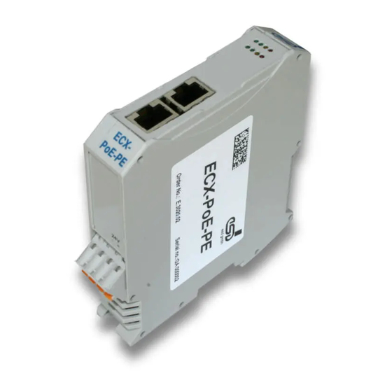
ECX-PoE-PE
Power-Extractor for InRailBus
Hardware Manual
to Product E.3020.02
ECX-PoE-PE
Page 1 of 25
Manual • Doc.-No.: E.3020.21 / Rev. 1.0
esd electronic system design gmbh
Vahrenwalder Str. 207 • 30165 Hannover • Germany
www.esd.eu • Fax: 0511/37 29 8-68
Phone: 0511/37 29 80 • International: +49-5 11-37 29 80
Advertisement
Table of Contents

Subscribe to Our Youtube Channel
Related Manuals for ESD ECX-PoE-PE


Summary of Contents for ESD ECX-PoE-PE
- Page 1 Page 1 of 25 Manual • Doc.-No.: E.3020.21 / Rev. 1.0 esd electronic system design gmbh Vahrenwalder Str. 207 • 30165 Hannover • Germany www.esd.eu • Fax: 0511/37 29 8-68 Phone: 0511/37 29 80 • International: +49-5 11-37 29 80...
- Page 2 gmbh.
- Page 3 Document- I:\Texte\Doku\MANUALS\ECX\ECX-PoE-PE\English\ECX-POE-PE_Hardware_en_10.wpd File: 2011-02-22 Date of print: from ECX-PoE-PE Rev. 1.0 PCB version: from Rev. 2.6 Firmware version: Changes in the chapters The changes in the document listed below affect changes in the hardware and firmware as well as changes in the description of facts only.
-
Page 4: Safety Instructions
Intended Use The intended use of the ECX-PoE-PE is the operation as a power extractor for InRailBus, applicable with ECX and CBX units. The esd guarantee does not cover damages which result from improper use, usage not in accordance with regulations or disregard of safety instructions and warnings. -
Page 5: Table Of Contents
7. Order Information ............25 ECX-PoE-PE Page 5 of 25 Manual •... - Page 6 This page is intentionally left blank. Page 6 of 25 ECX-PoE-PE Manual • Doc.-No.: E.3020.21 / Rev. 1.0...
-
Page 7: Overview
ϑ Fig. 1: Block circuit diagram of the ECX-PoE-PE module The ECX-PoE-PE is a power extractor that provides 24 V power supply voltage for the InRailBus. It can be used for ECX and CBX units. The power supply voltage is fed via the Ethernet lines (PoE). - Page 8 Fig. 2: Exemplary installation of the ECX-PoE-PE The ECX-PoE-PE receives the Ethernet data and the power supply for the InRailBus from the Power Source Equipment (PSE). The 24 V power supply voltage is fed into the InRailBus and the Ethernet data is electrically passed through to the Powered Devices (PD), e.g.
-
Page 9: Technical Data
Plastic housing for carrier rail mounting NS35/7,5 DIN EN 60715 width: 22.5 mm, length: 99 mm, constructional height: 114.5 mm Dimensions (dimensions without mating connectors) Weight approx. 135 g Table 1: General technical data ECX-PoE-PE Page 9 of 25 Manual • Doc.-No.: E.3020.21 / Rev. 1.0... -
Page 10: Microcontroller
(10/100/1000BASE-T), electrically passed through according to IEEE 802.03at (PoE+, only layer 1 is supported), PoE supply and compatible with IEEE 802.03 af (Class 4) Table 3: Data of analog inputs Page 10 of 25 ECX-PoE-PE Manual • Doc.-No.: E.3020.21 / Rev. 1.0... -
Page 11: Hardware Installation
Hardware Installation 3. Hardware Installation 3.1 Connecting Diagram Fig. 3: Connections of the ECX-PoE-PE module The connector pin assignment can be found on page 20 and following. Note: For the connection of the Ethernet interfaces use cables of type: unshielded twisted-pair, minimum Cat 5 U/UTP cable... -
Page 12: Led Display
1 2 3 W Fig. 4: Position of the LEDs in the front panel The ECX-PoE-PE module is equipped with 8 LEDs. The indicator states are described in the following chapters. The system LED S indicates the state of the system power. All other LEDs only indicate, if the power supply voltage is fed via the Ethernet lines (PoE). -
Page 13: Operation Of The Poe Leds P
Display function LED-Name Indicator Schmatics Label Name Colour Description Diagram state Temperature OK Temperature blinking Temperature Warning LED320D Temperature Error Table 6: Indicator states of the red temperature LED ECX-PoE-PE Page 13 of 25 Manual • Doc.-No.: E.3020.21 / Rev. 1.0... -
Page 14: Operation Of The Current Leds 1, 2, 3 And W
PSE PSE according to 802.3at (PoE+ = 25 W), I = 1.042 A PSE according to 802.3af (PoE = 12.5 W), I = 0.520 A Page 14 of 25 ECX-PoE-PE Manual • Doc.-No.: E.3020.21 / Rev. 1.0... -
Page 15: Power Derating Depending On The Mounting Position
Hardware Installation 3.3 Power Derating Depending on the Mounting Position The power derating of the ECX-PoE-PE depends on the mounting position of the ECX-PoE-PE module (EUT) and the neighbouring modules (P1, P2) on the mounting rail. The following examples show the measured power derating depending on the mounting position. -
Page 16: Installation Of The Module Using Inrailbus Connector
Please note the safety instructions containing the requirements on power supply current (see page 4). The power supply voltage of the ECX-PoE-PE is supplied via the Ethernet lines. The ECX-PoE-PE supplies the 24 V power supply voltage for the InRail Bus. Alternatively the 24 V power supply voltage can be supplied via the +24V power supply connector. -
Page 17: Module Installation Using A Mounting Rail Bus Connector
The bus connectors can be plugged together before or after mounting the ECX module. 2. Place the ECX module with the DIN rail guideway on the top edge of the mounting rail (see following figure). ECX-PoE-PE Page 17 of 25 Manual • Doc.-No.: E.3020.21 / Rev. 1.0... - Page 18 Now the module is mounted on the mounting rail and connected to the InRailBus via the bus connector. Connect the bus connectors and the InRailBus if not already done. Figure 8: Mounted ECX-module Page 18 of 25 ECX-PoE-PE Manual • Doc.-No.: E.3020.21 / Rev. 1.0...
-
Page 19: Connecting Power Supply To Inrailbus
3.5 Remove the ECX Module from the InRailBus If the ECX module is connected to the InRailBus please proceed as follows: 1. Disconnect the Ethernet lines ETH and ETH/PoE from the ECX-PoE-PE. 2. If applicable disconnect the +24 V power supply connector. -
Page 20: Connector Assignment
(+ 24 V) (GND) (GND) (+ 24 V) Please refer also to the connecting diagram on page 11. Signal Description: P24... power supply voltage +24 V M24... reference potential Page 20 of 25 ECX-PoE-PE Manual • Doc.-No.: E.3020.21 / Rev. 1.0... -
Page 21: Eth (X400)
Pin Position: Pin Assignment: Signal (GND) (+24 V) (PE_GND) Signal Description: P24... power supply voltage +24 V M24... reference potential FE... functional earth contact (EMC)(connected to mounting rail potential) ECX-PoE-PE Page 21 of 25 Manual • Doc.-No.: E.3020.21 / Rev. 1.0... -
Page 22: Ethernet (X110, X120)
Ethernet data and power lines of port ETH/PoE (X ... A, B, C or D), connected with PSE ETH2 X+/- Ethernet data lines of port ETH (X ... A, B, C or D), connected with PD Page 22 of 25 ECX-PoE-PE Manual • Doc.-No.: E.3020.21 / Rev. 1.0... -
Page 23: Quick Start Guide
Step page Read the safety notes at the beginning of the manual carefully before you start with the installation! Mount the ECX-PoE-PE module Connect the interfaces (ETH/PoE, ETH) End of hardware installation ECX-PoE-PE Page 23 of 25... -
Page 24: Declaration Of Conformity
6. Declaration of Conformity Page 24 of 25 ECX-PoE-PE Manual • Doc.-No.: E.3020.21 / Rev. 1.0... -
Page 25: Order Information
Order Information 7. Order Information Type Features Order No. Power Extractor for InRailBus with ECX and CBX ECX-PoE-PE E.3020.02 units Manuals Manual in English C.3020.21 ECX-PoE-PE-ME Accessories CAN-CBX-TBUS Mounting-rail bus connector of the CBX-InRailBus for CAN-CBX-modules, C.3000.01 (one bus connector is included in delivery of the...
Need help?
Do you have a question about the ECX-PoE-PE and is the answer not in the manual?
Questions and answers