Table of Contents
Advertisement
Quick Links
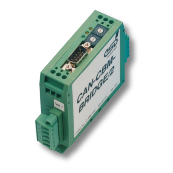
CAN-CBM-Bridge/2
Intelligent CAN-Bridge
Hardware Manual
to Product C.2853.02
CAN-CBM-Bridge/2
Hardware Manual • Doc. No.: C.2853.21 / Rev. 1.4
Page 1 of 41
esd electronic system design gmbh
Vahrenwalder Str. 207 • 30165 Hannover • Germany
http://www.esd.eu
Phone: +49 (0) 511 3 72 98-0 • Fax: +49 (0) 511 3 72 98-68
Advertisement
Table of Contents

Related Manuals for ESD CAN-CBM-Bridge/2


Summary of Contents for ESD CAN-CBM-Bridge/2
- Page 1 CAN-CBM-Bridge/2 Hardware Manual • Doc. No.: C.2853.21 / Rev. 1.4 Page 1 of 41 esd electronic system design gmbh Vahrenwalder Str. 207 • 30165 Hannover • Germany http://www.esd.eu Phone: +49 (0) 511 3 72 98-0 • Fax: +49 (0) 511 3 72 98-68...
- Page 2 The information in this document has been carefully checked and is believed to be entirely reliable. esd makes no warranty of any kind with regard to the material in this document, and assumes no responsibility for any errors that may appear in this document. In particular descriptions and technical data specified in this document may not be constituted to be guaranteed product features in any legal sense.
- Page 3 Note on terminal programs changed 2016-11-01 Examples revised, description of commands 'Reset' and 'Help' and 'Show rotary switch state' inserted Technical details are subject to change without further notice. CAN-CBM-Bridge/2 Hardware Manual • Doc. No.: C.2853.21 / Rev. 1.4 Page 3 of 41...
- Page 4 This NOTICE statement contains the general mandatory sign and gives information that must be heeded and complied with for a safe use. INFORMATION INFORMATION Notes to point out something important or useful. Page 4 of 41 Hardware Manual • Doc. No.: C.2853.21 / Rev. 1.4 CAN-CBM-Bridge/2...
-
Page 5: Safety Instructions
● When working with the CAN-CBM-Bridge/2 follow the instructions below and read the manual carefully to protect yourself from injury and the CAN-CBM-Bridge/2 from damage. ● Do not use damaged or defective cables to connect the CAN-CBM-Bridge/2 and follow the CAN wiring hints in chapter: "Correct Wiring of Electrically Isolated CAN Networks". - Page 6 The intended use of the CAN-CBM-Bridge/2 is the operation as intelligent CAN-Bridge, that links two independent CAN networks. The guarantee given by esd does not cover damages which result from improper use, usage not in accordance with regulations or disregard of safety instructions and warnings.
-
Page 7: Table Of Contents
Serial Interface........................13 3.5 Software..........................14 Description of the Units......................15 4.1 CAN............................. 15 Serial Interface........................16 4.2.1 Default Setting of CAN-CBM-Bridge/2 Module............16 4.2.2 Configuration....................... 16 4.2.3 Connecting the Serial Interfaces..................16 Function of Coding Switches....................17 Display......................... 18 Configuration of the CAN-CBM-Bridge/2..................19... - Page 8 Support by esd........................39 Declaration of Conformity......................40 Order Information........................41 Page 8 of 41 Hardware Manual • Doc. No.: C.2853.21 / Rev. 1.4 CAN-CBM-Bridge/2...
-
Page 9: Overview
Figure 1: Block circuit diagram of CAN-CBM-Bridge/2 The module CAN-CBM-Bridge/2 can connect two independent CAN nets. The nets can be operated with different bit rates. The module works with a MB90F453 microcontroller which buffers CAN data into a local SRAM. -
Page 10: Front View With Connectors And Coding Switches
For conductor connection and conductor cross section see page 29. NOTICE Read chapter “Hardware Installation ” on page 11, before you start with the installation of the hardware! Page 10 of 41 Hardware Manual • Doc. No.: C.2853.21 / Rev. 1.4 CAN-CBM-Bridge/2... -
Page 11: Hardware Installation
T-connectors and termination connectors for external termination. Additionally the CAN_GND signal has to be connected to earth at exactly one point in the CAN network. All esd termination devices will provide a corresponding contact. For details please read chapter “Correct Wiring of Electrically Isolated CAN Networks”. -
Page 12: Technical Data
Table 1: General data of the module 3.2 Microcontroller Unit Microcontroller MB90F543 SRAM: intern in MB90F543, 6 kbyte Memory Flash-EPROM: intern in MB90F543, 128 kbyte EEPROM: serial SPI-EEPROM Table 2: Microcontroller Units Page 12 of 41 Hardware Manual • Doc. No.: C.2853.21 / Rev. 1.4 CAN-CBM-Bridge/2... -
Page 13: Can Interface
3.4 Serial Interface Controller MB90F543 RS232 , Physical Interface only the signals RxD, TxD and GND are supported Connector 9-pin DSUB Table 4: Data of the serial interface CAN-CBM-Bridge/2 Hardware Manual • Doc. No.: C.2853.21 / Rev. 1.4 Page 13 of 41... -
Page 14: Software
13 in direction from net 0 to net 1 and can be set individually 13 in direction from net 1 to net 0 Table 5: Performance features of the software Page 14 of 41 Hardware Manual • Doc. No.: C.2853.21 / Rev. 1.4 CAN-CBM-Bridge/2... -
Page 15: Description Of The Units
ENABLE CAN_L GNDin GNDout CTX0 BUSL CAN_H CRX0 BUSH Optical Coupler HCPL7710 R/GND CAN_GND Microcontroller VCCin VCCout n.c. ENABLE n.c. GNDout GNDin Figure 3: CAN interface CAN-CBM-Bridge/2 Hardware Manual • Doc. No.: C.2853.21 / Rev. 1.4 Page 15 of 41... -
Page 16: Serial Interface
NONE 4.2.2 Configuration The serial interface is controlled by microcontroller MB90F543. The bitrate is 9600 Baud. Set the user’s terminal / PC to this value. The bitrate can not be changed at the CAN-CBM-Bridge/2 module. 4.2.3 Connecting the Serial Interfaces Below, the wiring of the serial interface is shown. -
Page 17: Function Of Coding Switches
(see chapter ‘Configuration of the CAN-CBM-Bridge/2’, from page 19). For this both coding switches have to be set to ‘0’ when the module is switched on (power on). During configuration and operation the coding switches are not evaluated, therefore it is recommendable to leave them set to ‘0’... -
Page 18: Led Display
LED 141 yellow status CAN 1 flashing CAN-error (such as bus off) power supply ‘off’ LED 140 green power shining power supply ‘on’ Table 7: LED status Page 18 of 41 Hardware Manual • Doc. No.: C.2853.21 / Rev. 1.4 CAN-CBM-Bridge/2... -
Page 19: Configuration Of The Can-Cbm-Bridge/2
The serial interface of the PC has to be configured with the values which are described in chapter “Default Setting of CAN-CBM-Bridge/2 Module”, (page 16). NOTICE At the module CAN-CBM-Bridge/2 both coding switches must be set to ‘0’ at power on! Settings unequal ‘0’ are only permitted for ‘Customized Configuation’ (see page 17). 5.1.1 Commands After the power supply has been switched on the CAN-CBM-module wakes up and puts out a message in the terminal program. - Page 20 Configuration of the CAN-CBM-Bridge/2 Bn:HexIndex By means of the command you can configure the desired bit rate of the CAN net with net number , with: for net 0 for net 1 If values between 0 to 0xF are specified for HexIndex, the bit rate is configured...
- Page 21 Configuration of the CAN-CBM-Bridge/2 I0:ID net 0 I1:ID net 1 This command assigns an identifier of CAN net 1 to an identifier of CAN net 0. The identifier ID net 0, which is received by CAN net 0 is assigned to identifier ID net 1 of CAN net 1.
- Page 22 Configuration of the CAN-CBM-Bridge/2 Mm:n:zzzzzzzzzzzzzzzzzzzzzzzzzzzzzz This command defines masks for identifiers. This way all identifiers or particular areas of identifiers can be assigned. Here is: 0,1... net in which the identifiers are to be received 0,1... net in which the filtered CAN frames are to be transmitted z...z:...
- Page 23 Configuration of the CAN-CBM-Bridge/2 The current configuration of the CAN-CBM-Bridge/2 module from the previous examples can be displayed by means of command Input: >Enter< Output: B0:6 I0:200 I1:300 I0:23456789 I1:543 M0:1:0000000000000000000000xxxxxxx1 B1:D I1:24567893 I0:205 After the configuration has been successfully completed, the configured data is stored in the configuration memory by means of command .
-
Page 24: Change Existing Configurations
Configuration of the CAN-CBM-Bridge/2 With the commands a help text can be shown, which contains a list of the available commands. Input: >Enter< Output: C - Clear all settings and deactivate bridge E - Store all settings to EEPROM and activate them R - Read/Show all settings B<net>:<baud>... -
Page 25: Connector Assignments
The assignment of the 9-pin DSUB-connector and the cable plug is designed according to CiA 303 part 1. Figure 5: Adapter cable 5-pole plug component to 9-pole DSUB CAN-CBM-Bridge/2 Hardware Manual • Doc. No.: C.2853.21 / Rev. 1.4 Page 25 of 41... -
Page 26: Rs-232 Interface (X100)
Device connector: 9-pin DSUB connector, male Pin Position: Pin Assignment: Signal Signal n.c. n.c. RxD (input) n.c. TxD (output) n.c. n.c. n.c. n.c..not connected Page 26 of 41 Hardware Manual • Doc. No.: C.2853.21 / Rev. 1.4 CAN-CBM-Bridge/2... -
Page 27: Access Line For The Serial Interface
Connector Assignments 6.3 Access line for the serial Interface Below the access line of the serial interface (RS-232) of the CAN-CBM-Bridge/2 to a PC is shown. DSUB female DSUB female 9-pole 9-pole (PC) (CAN-CBM-Module) local signal names used at CAN-CBM-Module... -
Page 28: Power Supply (X101, Uegm)
6.4 Power Supply (X101, UEGM) DANGER The CAN-CBM-Bridge/2 may only be driven by power supply current circuits, that are contact protected. A power supply, that provides a safety extra-low voltage (SELV or PELV) according to EN 60950-1, complies with this conditions. -
Page 29: Conductor Connection/Conductor Cross Sections
TWIN ferrules with plastic sleeve, min./ max. Minimum AWG according to UL/cUL Maximum AWG according to UL/cUL Technical Data from Phoenix Contact website, printed circuit board connector, plug component CAN-CBM-Bridge/2 Hardware Manual • Doc. No.: C.2853.21 / Rev. 1.4 Page 29 of 41... -
Page 30: Correct Wiring Of Electrically Isolated Can Networks
Therefore the practical maximum number of nodes, bus length and stub length are typically much lower. esd has concentrated her recommendations concerning CAN wiring on the specifications of the ISO 11898-2. Thus this wiring hints forgoes to describe the special features of the derived standards CANopen, ARINC825, DeviceNet and NMEA2000. -
Page 31: Light Industrial Environment (Single Twisted Pair Cable)
7.2.1 General Rules NOTICE esd grants the EU Conformity of the product, if the CAN wiring is carried out with at least single shielded single twisted pair cables that match the requirements of ISO 11898-2. Single shielded double twisted pair cable wiring as described in chapter 7.3. ensures the EU Conformity as well. -
Page 32: Cabling
9-pin DSUB-termination connectors with integrated termination resistor and male and ● female contacts are available from esd (order no. C.1303.01). DSUB termination connectors with male contacts (order no. C.1302.01) or female contacts ● (order no. C.1301.01) and additional functional earth contact are available, if CAN termination and grounding of CAN_GND is required. -
Page 33: Heavy Industrial Environment (Double Twisted Pair Cable)
CAN_L CAN_GND wire shield n.c. n.c. connector case connector case Shield n.c. = not connected earth (FE) Figure 10: CAN wiring for heavy industrial environment CAN-CBM-Bridge/2 Hardware Manual • Doc. No.: C.2853.21 / Rev. 1.4 Page 33 of 41... -
Page 34: Device Cabling
DSUB9 connector from ERNI (ERBIC CAN BUS MAX, order no.:154039). The usage of esd’s T-connector type C.1311.03 is not recommended for single shielded double twisted pair cables because the shield potential of the conductive DSUB housing is not looped through this T-connector type. -
Page 35: Electrical Grounding
5000 Table 9: Recommended cable lengths at typical bit rates (with esd-CAN interfaces) Optical couplers are delaying the CAN signals. esd modules typically reach a wire length of ● 37 m at 1 Mbit/s within a proper terminated CAN network without impedance disturbances like e.g. -
Page 36: Examples For Can Cables
Correct Wiring of Electrically Isolated CAN Networks 7.6 Examples for CAN Cables esd recommends the following two-wire and four-wire cable types for CAN network design. These cable types are used by esd for ready-made CAN cables, too. 7.6.1 Cable for light industrial Environment Applications (Two-Wire) -
Page 37: Can Troubleshooting Guide
- there are no open circuits in CAN_H or CAN_L wiring - your bus system has two terminating resistors (one at each end) and that they are 120 Ω each. CAN-CBM-Bridge/2 Hardware Manual • Doc. No.: C.2853.21 / Rev. 1.4 Page 37 of 41... -
Page 38: Electrical Grounding
(see figure at previous page). 4. Measure the DC voltage between CAN_L and CAN_GND (see figure at previous page). Normally the voltage should be between 2.0 V and 3.0 V. Page 38 of 41 Hardware Manual • Doc. No.: C.2853.21 / Rev. 1.4 CAN-CBM-Bridge/2... -
Page 39: Can Transceiver Resistance Test
If you have executed the fault diagnostic steps of this troubleshooting guide and you even can not find a solution for your problem our support department will be able to assist. Please contact our support via email at support@esd.eu or by phone +40-511-37298-130. CAN-CBM-Bridge/2 Hardware Manual •... - Page 40 CAN Troubleshooting Guide 9. Declaration of Conformity Page 40 of 41 Hardware Manual • Doc. No.: C.2853.21 / Rev. 1.4 CAN-CBM-Bridge/2...
- Page 41 Table 10: Order information PDF Manuals Manuals are available in English and usually in German as well. For availability of English manuals see table below. Please download the manuals as PDF documents from our esd website www.esd.eu for free. Manuals Order No.
Need help?
Do you have a question about the CAN-CBM-Bridge/2 and is the answer not in the manual?
Questions and answers