
Subscribe to Our Youtube Channel
Related Manuals for EVA EVAstream FIT


Summary of Contents for EVA EVAstream FIT
- Page 1 EVA Wiring diagrams EVAstream & DMX (P3 - P4) EVAstream & Piezo (P5 – P9) EVAstream & ECA-PRO (P10 – P13) EVA RGBW lighting (P14 – P16) EVA Tech B.V. De Velde 1 8064 PH Zwartsluis The Netherlands www.evastream.nl Wiring Diagrams V22.3...
-
Page 2: Safety Warnings
Safety warnings WARNING! Switch off all relevant live cables before starting installation. RISK OF ELECTRIC SHOCK OR INJURY. The EVAstream and its control accessories must be installed by a certified electrician in accordance with applicable local rules and regulations. Incorrect installation can cause electrical hazards. CAUTION! Carefully read the separately enclosed document “Safety instructions mounting &... -
Page 3: Motor Control Unit
Motor Control Unit | DMX Ready Article: EVA-SP-xxx-MCU-DMX For connecting DMX control advanced (EVA-AA-77SL) or ADV) EVA ECA Controller (SP/EVA-ECA-PRO) With Piezo/DMX Advanced (EVO) Control start address = 5 Always cut off power before servicing the engine Wiring Diagrams V22.3... - Page 4 Wiring Diagrams V22.3...
- Page 5 Motor Control Unit | Piezo Ready Article: EVA-SP-xxx-MCU-PIEZO ADV) Always cut off power before servicing the engine Wiring Diagrams V22.3...
- Page 6 Wiring Diagrams V22.3...
- Page 7 (piezo 1 or 2 or 3 --> make selection within 5 seconds otherwise step 2 is skipped, automatic proceeding to step 3) When using an EVA DMX controller as master, * In training mode (step 2) piezo 1 = speed +, piezo 2 = standby, piezo 3 = speed -. In standy piezo 3 = off use DMX start address 5 * In stap 3 (stap 2 skipped) piezo 1 = speed +, piezo 2 = standby, piezo 3 = speed -.
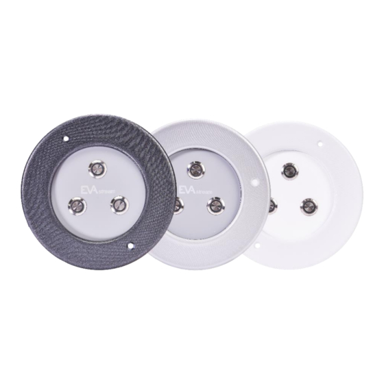
- Page 8 EVA Piezo3 | Wiring diagram for Piezo3 (7-wired cable) to SP-PIEZO-ADV-PCB / SP-PIEZO-PSU-ADV (EVAstream Piezo PCB) Article: SP-PIEZO3-W, SP-PIEZO3-G or SP-PIEZO3-A Connect wires (7-wired cable) according to schematics below, use wire colours as indicated: Wiring Diagrams V22.3...
- Page 9 For cable extension, use data cable with minimum conductor size 0,25mm2 and with a maximum cable length of 30 meters. Recommended cable type LiYY 16 x 0,25mm2 (Lapp Unitronic) or equal. It is allowed to connect EVA-PIEZOSQ4-AMB-X and SP-PIEZO3-X parallel to SP-PSU-ADV. It is also possible to combine wires 7,9,11,13,15,17,19,21 to: Piezo 4 switch sw 9.
- Page 10 Motor Control Unit | ECA Ready PER 01-06-2022 STANDARD for EVAstream SET Article: EVA-SP-xxx-MCU-ECA EVA Experience Controller wiring schematic: see manual Article code: SP/EVA-ECA-PRO Always cut off power before servicing the engine Wiring Diagrams V22.3...
- Page 11 Wiring Diagrams V22.3...
- Page 12 Piëzo 2 = pass / pause DMX signal (note! the turbine pauses, but the scene continues in the DMX master) Piëzo 1 = slow down Controlling EVA Lighting by piëzo without APP Piëzo 3 = speed up to maximum speed of the chosen scene (f.e. scene 70% : the maximum speed in this scene is 70%).
- Page 13 EVA Piezo3 | Wiring diagram for Piezo3 (7-wired cable) to SP-ECA-PRO / EVA-ECA-PRO (Experience Controller PCB) >II Article: SP-PIEZO3-A, SP-PIEZO3-G or SP-PIEZO3-W Connect wires (7-wired cable) according to schematics below, use wire colours as indicated: Piëzo control EVAstream incl. EVA lighting (by APP)
- Page 14 EVA RGBW LED driver | Wiring Diagram LED driver 4+2 channel for EVA RGBW lighting Article: SP-DR-DMX-4CH Wire colour for each Piezo type different Couleur de fil différente pour chaque type de piézo Connect wires according to schematics below, use wire colors as indicated: Color de cable diferente para cada tipo piezoeléctrico...
- Page 15 Connect wires (7-wired cable) according to schematics below, use wire colors as indicated: Set the 4-channel EVA LED Driver (SP-DR-DMX-4CH), to which the Piezo Controller is being connected, to Master mode (rotary address 600). Connect the other lights via DMX in/out. Set these to Slave mode (rotary address 001).
- Page 16 L: 81 mm Set the 4-channel EVA LED Driver (SP-DR-DMX-4CH), to which the Piezo Controller is being connected, to Master mode (rotary address 600). Connect the other lights via DMX in/out. Set these to Slave mode (rotary address 001).
Need help?
Do you have a question about the EVAstream FIT and is the answer not in the manual?
Questions and answers