Aranet PRO User Manual
Hide thumbs
Also See for PRO:
- User manual (97 pages) ,
- Quick start manual (9 pages) ,
- Quick start manual (7 pages)

Related Manuals for Aranet PRO


Summary of Contents for Aranet PRO
- Page 1 USER GUIDE Aranet PRO/Aranet PRO+ Applicable for Aranet PRO/Aranet PRO+ with firmware starting from v.3.0.1 Document revision v.9 July 2022...
- Page 2 Changes or modifications not expressly approved by the party responsible for compliance could void the user’s authority to operate the equipment. Aranet PRO/PRO+ does not contain serviceable parts. Warranty will not be applicable in the event of Aranet PRO has been opened or Aranet PRO+ warranty seals are damaged.
- Page 3 Industry Canada Regulatory Statement This device complies with Industry Canada’s license-exempt RSSs. Operation is subject to the following two conditions: 1. This device may not cause interference; and 2. This device must accept any interference, including interference that may cause undesired operation of the device.
-
Page 4: Table Of Contents
Emergency switching off ARANET PRO/PRO+ SPECIFICATIONS INITIAL SETUP Initial setup of Aranet PRO/Aranet PRO+ 2.1.1 Initial setup of Aranet PRO/Aranet PRO+ using built-in Wi-Fi Access Point 2.1.2 Initial setup of Aranet PRO/Aranet PRO+ using Ethernet cable 2.1.3 Initial Login and Fast Settings... - Page 5 3.6.13 SNMP menu Integrations 3.7.1 MQTT 3.7.2 Aranet Cloud 3.7.3 Modbus SENSORS’ SPECIFIC NOTES 4.1.1 Weight Sensor 4.1.2 Soil (Substrate) Sensor 4.1.3 4-20 mA and Voltage Sensors 4.1.4 Stem Micro-Variation sensor 4.1.5 Ultrasonic Distance sensor 4.1.6 CO2 and Temperature sensor 4.1.7...
-
Page 6: Introduction
1 INTRODUCTION Aranet offers environmental monitoring solutions for a variety of businesses. Aranet PRO and Aranet PRO+ are industrial grade environment monitoring solutions. Aranet PRO/PRO+ can support 12, 50 or 100 sensors depending on license purchased. The base station has exceptional sensitivity and allows placing the sensors within line-of-sight range of at least 3km/1.9mi. -
Page 7: Aranet Pro Base Overview
ARANET PRO BASE OVERVIEW 1.1.1 What’s in the box 1 pc of Aranet PRO base station with installed Aranet SensorHUB software and License 1 pc of Aranet PRO base station mount 2 pcs of W1412 screws 1 pc of AC power adapter (EU or US version depending on product version) -
Page 8: Aranet Pro Indicators
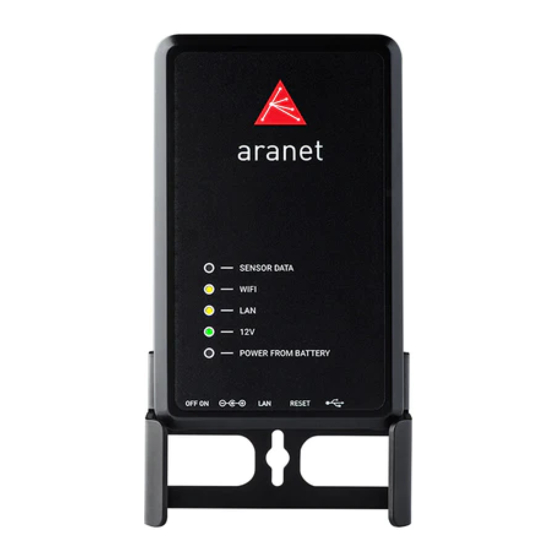
(3) LAN connection indicator LED – amber light when Aranet PRO is connected to LAN connection through an Ethernet cable (4) 12V power indicator LED – green light when Aranet PRO is connected to 12V power either through a PoE connection or with the included AC power adapter (5) Battery power indicator LED –... -
Page 9: Aranet Pro Mounting
Base station mount configuration for placement on horizontal surface (e.g., table). 1.1.4 Aranet PRO ports (1) On-Off switch – switch in the left position means Aranet PRO is turned off, switch in the right position means Aranet PRO is turned ON (2) AC Power port - for using the included AC power adapter to power Aranet PRO (3) Ethernet port –... -
Page 10: Aranet Pro Power Options
1.1.6 Internal battery backup Aranet PRO is supplied with built in battery backup providing up to 30 minutes of power supply in case of main power failure. It is meant only as a backup and allows Aranet PRO to shut down safely. System warning (if enabled) will be issued in case of main power failure and before Aranet PRO switches off completely. -
Page 11: Aranet Pro+ Base Overview
1.2 ARANET PRO+ BASE OVERVIEW 1.2.1 What’s in the box 1 pc of Aranet PRO+ base station with installed Aranet SensorHUB software and License 1 pc of Cat.5 Ethernet cable 1m Page 11... -
Page 12: Aranet Pro+ Front View
1.2.2 Aranet PRO+ front view IP68 protected RJ-45 Ethernet port for Network and Power connection. Screws for detaching/securing Aranet PRO+ case lid – 4 pcs. Warranty seals - Nylon screws – 4 pcs. Warranty is lost if damaged. SIM-card holder (P/N TDSBOB03, TDSBOBU3, TDSBOBC3 only). -
Page 13: Aranet Pro+ Indicators
System indicator – green light when Aranet PRO+ system is started. Power indicator LED – green light when Aranet PRO+ is powered. 1.2.4 Aranet PRO+ mounting Aranet PRO+ case has four dedicated holes for 4…4.5 mm screws by which base can be mounted to smooth surface: Page 13... -
Page 14: Sim-Card Installation
PoE insert. 1.2.7 Emergency switching off Aranet PRO+ can shut down and switch off safely in case of main power failure. System notification will be sent as email and/or SMS to the destination configured by users belonging to the Administrator group. -
Page 15: Aranet Pro/Pro+ Specifications
1.3 ARANET PRO/PRO+ SPECIFICATIONS Aranet PRO Aranet PRO+ TDSBWB01, TDSBWBU1, TDSBOB03, TDSBOA03, TDSBWBC1, Part Number (P/N) TDSBOBU3, TDSBOAU3, TDSBWPA1.xxx, TDSBOBC3 TDSBOAC3 TDSBWPA2.xxx, TDSBWPC2.xxx Maximum sensor 100/50/12 count* Alarm type Email SMS notification Optional alarm through external SMS notification USB modem... - Page 16 AC/DC power Included adapter, mounting Cat.5 Ethernet cable 1 m bracket Additional – Europe Aranet MINI can be used as a monitor * Depending on license purchased ** Aranet4 PRO sensor with 5-minute TX interval chosen for calculation. Page 16...
-
Page 17: Initial Setup
2.1 Initial setup of Aranet PRO/PRO+ Aranet PRO/Aranet PRO+ can be configured with built-in Wi-Fi Access Point or with Ethernet connection to local network. This allows quick and easy access to Aranet PRO using any personal devices like PC, tablet, or smartphone. -
Page 18: Initial Setup Of Aranet Pro/Aranet Pro+ Using Ethernet Cable
Aranet PRO: Plug in included AC power adapter jack and switch base on using On-Off switch, plug in Ethernet cable that connects Aranet PRO directly to your PC. Switch Aranet PRO on. Wait until LED indicators next to “12V” and “LAN” turn on and wait for another 30 seconds. -
Page 19: Initial Login And Fast Settings
2.1.3 Initial Login and Fast Settings Username and password for login can be found on the label attached to Aranet PRO/PRO+ (see example below). Aranet PRO Mk2: Username: root Password: changeme !NOTE! Root is an administrator account. For security reasons, we recommend changing the password as soon as possible. - Page 20 It is a good practice to start with System settings. Click with your mouse to the Menu icon to open MAIN menu and select System: Navigate to Region menu and set your preferred Language, Units, Time, and Data formats. Click Save Page 20...
- Page 21 Navigate to Time menu and set time manually, synchronize with your PC or NTP. Click Save Navigate to Firmware menu. It is highly advised to install the latest firmware for your Aranet PRO/PRO+ base. Visit aranet.com/downloads/ to download the latest firmware version and upgrade your device if it has older firmware version installed.
- Page 22 Be patient, it is long-lasting process and can take up to 3 hours. You can skip scanning by now and select channel at your desire, but this can lead to less good communication between sensors and Aranet PRO/PRO+ base.
-
Page 23: Pair Sensors To Aranet Pro /Pro
2.2 Pair sensors to Aranet PRO /PRO+ Aranet PRO/PRO+ supports several types of sensors. To connect them to the system the same steps apply for all types of sensors. Sensors can be paired by-one or in batch. When pairing the sensor, it should be physically located within around 20 meters of Aranet PRO/PRO+. - Page 24 Observing the LED light indications can save time while pairing sensors, however, Aranet PRO/PRO+ software will also display successfully paired sensor in the sensors list: new sensors are indicated by green triangle. Sensor pairing process usually lasts 10-15 seconds but can be prolonged up to 30 seconds.
- Page 25 You have now paired sensors to Aranet PRO/PRO+ and can place it in the desired location. All paired sensors appear on the Home page of SensorHUB: The fast set-up process is finished. Page 25...
-
Page 26: Connecting Aranet Pro/Pro+ To Internet Network
Internet (or internal data (Local) network). 2.3.1 Connecting Aranet PRO/PRO+ to internet network using local Wi-Fi router In case you wish to connect your PC and Aranet PRO to your local Wi-Fi network, you should change Wi-Fi settings on Aranet PRO in following way: (1) Connect your PC to Aranet PRO/PRO+ using Ethernet cable (refer to chapter 2.1.2 Initial setup of... - Page 27 (8) After the new Wi-Fi settings on Aranet PRO/PRO+ are saved, web page will reload, and new IP address will be assigned by the external Wi-Fi router. You can see the new IP address displayed like shown in picture below (Wi-Fi IP: xxx.xxx.xxx.xxx). Note the globe symbol is not crossed, which indicates successful connectivity to the Internet.
-
Page 28: Connecting Aranet Pro/Pro+ To Internet Network Using External Router
Verify that LED indicators next to “12V” and “LAN” turn on. As factory setting, Aranet PRO/PRO+ DHCP client is ON. If there is working DHCP server in the network (as usually is when connecting to router), Aranet PRO/PRO+ will receive new IP address automatically. - Page 29 DHCP server’s assigned IP address for Aranet PRO/PRO+ Ethernet port is changed. Consult your network administrator or refer to the user manual of the external router on how to always reserve the same IP address assigned to the Aranet PRO/PRO+ Ethernet port (MAC address).
-
Page 30: Accessing The Aranet Pro/Pro+ From Internet
Graphs, set up Sensor Groups and alarms, Notifications sending, etc. For instructions, please read corresponding chapter in following ARANET SENSORHUB OVERVIEW. It is also possible to enable Aranet sensor data upload to Aranet Cloud - Plug & Play Cloud solution for Aranet IoT ecosystem. Page 30... -
Page 31: Aranet Sensorhub Overview
Main menu contains following sections - Home, Graph, Sensors, Groups, System, MQTT, Aranet Cloud, Modbus TCP/IP. From these sections you can navigate to all options of the Aranet PRO/PRO+ software. General information about the user login, current device time and date as well as log off option are displayed here. - Page 32 Click on the Sort button to open a sub-menu of measurement types. Click on a measurement type to sort by this measurement and hide sensors which do not provide it. Clicking on "Name" or "Group" will list all sensors. Click on to sort by name or value in descending order.
-
Page 33: Graphs
3.3 Graphs Graphs screen enables user to view, compare and analyze the data from the sensors. The “Graph” page enables user to look at historical data, patterns, and changes, as well as compare multiple sensor readings over time to see potential correlations. By pressing icon add up to 20 sensors at once for analysis one by one or use icon to add... - Page 34 On a computer the timeline zoom-in and zoom-out can be done using mouse scroll wheel while mouse pointer is positioned in the graph area (some application requires holding down the Control button (ctrl) while scrolling the mouse wheel). On a smartphone device it is possible to use multi touch and panning function with two fingers for navigation.
- Page 35 To display the measurement curves with more granularity, untick the Autoscale and choose the Min and Max values by moving the slide bars or typing in the required values. rearrange the order in which the graphs are displayed, drag the parameter boxes by the Move handle.
-
Page 36: Sensors
20. 3.5.1 Using groups You should be logged in using an account with administrative rights. To create a new group, go to Aranet PRO/PRO+ Main menu and choose the “Groups” menu. Click “Add group” Now the group can be renamed and thresholds for alarms can be set. These thresholds work for all sensors in the group, unless a sensor is specified to use its own threshold in sensor menu. - Page 37 To add sensors to a group, choose the “Sensors” menu and click on the item you would like to add. (Same is possible from main menu “Home”) In sensor options click on the group drop down menu. Choose the group you would like to add this sensor to.
-
Page 38: System
SAVE button. Aranet PRO/PRO+ device name will be used in the email notifications for easier identification of which Aranet PRO/PRO+ device is sending the message. Page 38... -
Page 39: Region Menu
3.6.2 Region menu The “Regional settings” menu is where the interface of Aranet PRO/PRO+ can be set up with the preferred language, temperature scale and time and date format settings. To apply new settings, click Save button. Page 39... -
Page 40: Time Menu
3.6.3 Time menu By default, Aranet PRO/PRO+ uses the local devices time settings, however it is possible to change the time and set it up manually, if it is preferred, as well as to use an NTP server for time synchronization. -
Page 41: Network Menu
3.6.4 Network menu The “Network settings” menu is where you can configure the connectivity of Aranet PRO/PRO+. Wi-Fi and Ethernet connectivity is supported for connecting to the internet; however, Ethernet connectivity is preferred for stability. It is also recommended to disable not used network interfaces to lower the processor load. - Page 42 In case you wish to connect Aranet PRO/PRO+ to a local Wi-Fi network choose the Client mode, find the appropriate Wi-Fi connection, and fill in the Wi-Fi password. Apply the changes by Save button. !NOTE! Most routers have DHCP enabled by default, we recommend keeping this setting for ease of set up.
- Page 43 NETWORK RESET. If Static IP fallback is switched OFF, no valid IP address is assigned to Aranet PRO/PRO+ Ethernet interface when it did not receive IP address from DHCP server. !NOTE! Most routers have DHCP enabled by default, we recommend keeping this setting for ease of set up.
- Page 44 Please consult your Mobile Internet provider for data to fill out connection configuration fields. It is possible to access Aranet PRO+ web interface from internet over LTE connection. For this purpose, please contact your Mobile Internet provider and request static IP-address for the SIM-card inserted into modem.
-
Page 45: Firmware Menu
Aranet PRO/PRO+ must be connected to internet. When navigating to this menu, Aranet PRO/PRO+ connects to SAF Tehnika server over HTTPS protocol TCP on port 443 to check for newer firmware version availability. If newer firmware version is released, notification is shown. - Page 46 The software update usually takes about two minutes to be completed. During that period, the device will reboot to complete the update. After the firmware upgrade, if the Aranet PRO/PRO+ web interface does not function properly, we recommend clearing the browser’s cache.
-
Page 47: Backup Menu
NETWORK RESET will load the default network settings for Aranet PRO/PRO+ and can also be performed by a network reset button on Aranet PRO/PRO+ by holding it for 5 or more seconds, however that will also reset the root user password. -
Page 48: Licenses Menu
3.6.8 Licenses menu List of purchased and installed Aranet PRO/PRO+ licenses is available here. To add new license to Aranet PRO/PRO+ base station click UPLOAD LICENSE button, select license file, and click OK. 3.6.9 Notifications “Notifications” menu offers management of alarms and summaries. Aranet PRO/PRO+ offers receiving alarms and summaries via e-mail notifications or text messages (SMS). - Page 49 An e-mail and/or SMS will be sent immediately or after the delay time set under “Notification delay” for the respective sensor. For setting a Notification delay navigate to the Main menu (Home) and click on required sensor. 3.6.9.2 Settings screen The Settings screen is where you can choose if you want to receive notifications via email, text messages or both, and what type of notification to receive.
- Page 50 Page 50...
- Page 51 Name of the sensor and name of group it belongs to. • Battery warnings. • Channel warnings (in case a sensor is using a different radio channel than the Aranet PRO base station). • Warnings about number of faulty data packets received.
- Page 52 LTE menu of this document for configuration. Aranet PRO: SMS functionality is enabled if you have a USB GSM modem with an active SIM card connected to Aranet PRO. Please find actual information about the supported (tested) GSM modems here: https://forum.aranet.com/aranet-solutions/what-cellular-usb-modems-are-compatible-with-aranet-pro-...
- Page 53 There is support for Gmail, Outlook, and Yahoo accounts, however a Custom SMTP provider can also be set up. For e-mail notifications to work, the Aranet PRO should have connectivity to mail server (internet or other data network). Please refer to chapter 3.6.4 Network...
-
Page 54: Radio Menu
If the area has a dense coverage of sensors from other base stations this can become important. !NOTE! If sensors are already paired to Aranet PRO/PRO+ they will also show up as interference in the radio scan of the channel currently in use. -
Page 55: Aranet Mini Monitor Mode
3.6.11 Aranet MINI monitor mode Aranet MINI monitor mode serves as a screen function displaying up to 12 sensor data. It can be used if constant display of the data readings is required from the sensors paired to Aranet PRO/PRO+. User can set as many Aranet MINI to Monitor mode, as necessary. - Page 56 Aranet Mini should be connected to a free USB port on the computer using for instance the included USB cable. It will automatically recognize Aranet Mini as a storage device. The downloaded file needs to be transferred to the Aranet Mini main file directory. New settings from configuration file will automatically be applied to Aranet MINI.
-
Page 57: Users Menu
3.6.12 Users menu The Users is where you can create new users, delete, and edit the data about existing ones. There are two types of account groups - User and Administrator. The User group account has limited access to many of the settings’ features, however full access to data and sensors is granted. -
Page 58: Snmp Menu
3.6.13 SNMP menu SNMP menu is where you setup Simple Network Management Protocol parameters for Aranet PRO/PRO+ health monitoring. Necessary enterprise specific (SAF-ENTERPRISE.MIB, SAF-ARANET-PRO.MIB) and additional trap event type and severity level definitions related (ITU-ALARM-TC.MIB, IANA-ITU-ALARM- TC.MIB) MIB files can be downloaded here. -
Page 59: Integrations
MQTT data reception), for example, account on Amazon AWS or Microsoft Azure cloud computing platforms. • Access to some MQTT broker that is necessary to obtain data from Aranet PRO/PRO+ base station and then send it to the user software. •... - Page 60 7) Root topic – allows selecting root topic name with what MQTT messages will be published from Aranet PRO/PRO+ base station on MQTT broker. In our example, we will use the name Aranet; 8) Sensor measurement format – allows selecting format (raw, JSON or Azure) in which MQTT messages from Aranet PRO/PRO+ base station will be published on MQTT broker;...
- Page 61 If configured MQTT connection is successful, then Connection successful message will be shown on the top of the page also showing the precise time when the connection was established. For more MQTT connections settings examples refer to https://aranet.com/software/ Page 61...
-
Page 62: Aranet Cloud
• User has any type of device with a working Internet connection and WEB browser installed on it. • User has access to an e-mail account that can be used for new account registration in the Aranet Cloud platform. •... - Page 63 3) Remember or copy to clipboard generated registration code; 4) Switch back to Aranet PRO/PRO+ webpage, make sure about Cloud service availability – icon must be green*, and type in or paste from clipboard e-mail address you are registered with in aranet.cloud, and generated registration code;...
- Page 64 The sensor data upload process depending on sensor data amount and data connection speeds between Aranet PRO/PRO+ base station and Aranet Cloud system can take up to 20 – 30 minutes. During this process sensor data will gradually appear in the Aranet Cloud organization.
-
Page 65: Modbus
It refers also to function codes. Only function code 4 is supported (read "Input register"). Aranet PRO/PRO+ appears in Modbus networks as server (slave) having its own server(slave) ID. By default, Aranet PRO/PRO+ server (slave) ID is “1”. - Page 66 Autogenerated Aranet PRO/PRO+ Modbus addresses layout file example. Most important explanations about addresses are given in downloaded json file as //comments: //////////////////////////////////////////////////////////////////////////////// // Aranet PRO Modbus mapping configuration description. // The configuration supports the inputRegisters protocol object type. // Each type has its own address offset value (e.g., 30000).
- Page 67 "dataType": "int32", "multiplier": 100 "rssi": { // Address 26: measurement rssi in dBm "offset": 6, "dataType": "int32", "multiplier": 1 "time": { // Address 28: measurement time in seconds "offset": 8, "dataType": "uint32", "multiplier": 1 //////////////////////////////////////////////////////////////////////////////// Autogenerated file can be used as template for Custom layout file creation: you can edit it to read needed sensors and measurements only.
-
Page 68: Sensors' Specific Notes
4 SENSORS’ SPECIFIC NOTES 4.1.1 Weight Sensor To reset the zero offset of weight (tare), click on the TARE button. The last measured tared and (untarred weight), as well as the date and time of the last tare event will be indicated. By default, the graph of the Weight Sensor will display measurements of a tared weight. -
Page 69: Soil (Substrate) Sensor
4.1.2 Soil (Substrate) Sensor The soil (substrate) Sensor displays the Temperature, Volumetric Water Content and Pore Water Electrical Conductivity measurement values. Under the “Sensors” menu it is possible to select the calibration of the VWC and EC (pore water) calculation method, by selecting Topp, Soilless, Mineral Soil or Rockwool. Should you require to modify the calibration curve, change the required calibration values. - Page 70 The graph of soil sensors by default displays Temperature, Volumetric Water Content and Pore Electrical Conductivity. Use the Tune button, to display the Bulk Electrical Conductivity and dielectric permittivity (ε). Page 70...
-
Page 71: Ma And Voltage Sensors
4.1.3 4-20 mA and Voltage Sensors The 4-20mA Sensor can be used for current measurements (within a range of 0 - 30 mA) and the Voltage Sensor - for voltage measurements (within a range of -32 to +32 VDC). Under the “Sensors” menu, it is possible to enable conversion from mA/V to other values depending on transducer type connected to mA/V Sensor. -
Page 72: Stem Micro-Variation Sensor
1. First existing stem diameter should be measured with a ruler or caliper (in our example 8mm): 2. Then sensor detecting element should be mounted on the stem: 3. Sensor electric current reading on Aranet PRO base station graphical user interface should be checked and recorded (in our example 5.12mA) - Page 73 9. Finally, previously obtained millimeter values for 4mA and 20mA should be entered in Stem Micro-variation sensor Conversion configuration in Aranet PRO base station graphical user interface section Sensors à SENSORS after that user will be able to see sensor measurements in mm of the stem diameter:...
- Page 74 Page 74...
-
Page 75: Ultrasonic Distance Sensor
Aranet Ultrasonic Distance sensor works with a wide range of liquid and non-liquid materials. Various practical applications of the sensor include measuring grain level in a silo, or the level of a liquid in a container, as well as other uses. -
Page 76: Co2 And Temperature Sensor
4.1.6 CO2 and Temperature sensor The sensor comes factory calibrated, but when recalibration is needed it can be done in the following steps: 1) Screw out top part of the sensor; 2) Small dipswitch on the PCB board should be set in position;... -
Page 77: Nh3 Sensor Kit
Kit consists of DOL53 sensor, wire junction box TDADCA01 and Aranet 0-10 VDC transmitter. Sensor and transmitter are connected to junction box which is powered by 220-240 VAC. In addition, Aranet 0-10V transmitter is powered by 1 AA size battery. -
Page 78: Legal Information
(including frequency range) of the customer’s home country or jurisdiction. WARRANTY TERM The Warranty shall apply to Aranet 24 months after it is shipped to the customer. An invoice itemizing a product’s warranty period shall be included with the product when it is delivered to the customer. No verbal extensions or modifications of the Warranty shall be enforceable. - Page 79 If the failure is discovered to a SAF manufactured product, it will be given a Return Materials Authorization (“RMA”) number and should be returned to SAF by completing the RMA form at https://aranet.com/rma/ and then shipping the non-functioning product in its original packaging (or packaging providing a similar level of protection) to one of the facilities below.
-
Page 80: Rma (Return Merchandise Authorization) Form
DOA. Any product discovered as non-functioning within 30 days after it is shipped to the customer, for any reason other than a customer’s misuse or mishandling, shall be deemed “Dead on Arrival” or “DOA” and replaced free of charge. Aranet products will be replaced no later than 20 business days after SAF verifies its non-functioning status. -
Page 81: Intellectual Property Rights
5.5 DATA SECURITY Aranet systems use encryption when the data is transmitted from the sensors to the base station. A unique encryption key is provided for each base station. The transmission protocol has built in safeguards against malicious operations (for example replay attacks). -
Page 82: Accessories
5.9 ADDITIONAL INFORMATION For additional information, please contact support@aranet.com SAF Tehnika JSC 24a, Ganibu Dambis Riga, LV-1005, Latvia ©...
Need help?
Do you have a question about the PRO and is the answer not in the manual?
Questions and answers