Subscribe to Our Youtube Channel
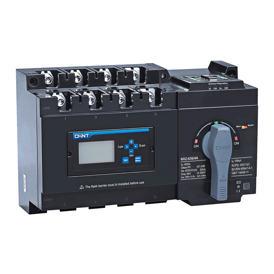
Summary of Contents for CHINT NXZ Series
- Page 1 NO:2021.04 NXZ Series Automatic Transfer Switch User Instructions Standard: IEC/EN 60947-6-1...
-
Page 2: Safety Warning
Safety Warning Only professional technicians are allowed for installation and maintenance. Installation in any damp, condensed-phase environment with inflammable and explosive gas is forbidden. You are prohibited from touching the conductive part when the product is operating. Do not install the product at places where gas medium can cause metal corrosion and insulatin damage. -
Page 3: Inspection And Test
NXZ Automatic Transfer Switch Applicatin Information a) The normal operating ambient temperature of the product is - 5 ℃ ~ + 40 ℃; Note: if it is used within the range of - 35 ℃ ~ + 70 ℃, please consult with the manufacturer. b) If the altitude exceeds 2,000m, please consult with the manufacturer;... - Page 4 NXZ Automatic Transfer Switch Manual debugging ① ② Double switch off position ③ ④ Normal switch on position Standby switch on position Figure 2 Manual debugging The installation, operation and maintenance of the product are only carried out by qualified professional. Power -on test AUTO +...
- Page 5 NXZ Automatic Transfer Switch + MANU + AUTO STOP AUTO AUTO MANU MANU Start-up mode of fire control Manual mode Figure 3-2 Power -on test Outline and Installation Size Outline and Installation Size of NXZ-125 630 H(max) A(max) + Normal Standby Duplexing Automatic...
-
Page 6: Installation And Wiring
NXZ Automatic Transfer Switch Installation and Wiring Installation method 4P product wiring diagram Normal power bus Alternative power bus. During wiring, incorrect N-pole wiring may result in the burn-out of the controller! Main circuit conductor 1 The phase sequence of normal and standby power supply must be consistent. - Page 7 NXZ Automatic Transfer Switch Wire connection ≥φc ≤a ≥φc ≤b ≤a ≤b Figure 6 Wire connection Tabla 3 Sectional area, width and number of copper wire Unit: mm Number of conductors allowed Cable specifications Product model to be clamped into the terminal NXZ-125 21.5 25~50mm...
- Page 8 NXZ Automatic Transfer Switch Signal and control terminal wiring Indication of alternative state Indication of normal state Active AC230V/0.5A The user should connect corresponding terminal as needed Control of power generation start-up Auxiliary power Fire control supply signal Note: The dash line refers to the internal circuit of controller Figure 7 Type A controller RS485...
- Page 9 NXZ Automatic Transfer Switch RS485 Figure 8 Type B controller Typical application Connected to upper computer (RS485) 1.Used in grid - power generation mode and may be omitted, but the delay of generator start-up defaults to 0s. 2.Communication terminal wiring must be connected. Normal neutral Alternative neutral Alternative power supply...
- Page 10 NXZ Automatic Transfer Switch 1. Any form of electrical connection is prohibited between the two groups of terminals; otherwise it may result in the burn-out of controller! Indication of alternative state Indication of normal state 2. Terminals 401 and 402 of type A and type B controllers can be connected with passive closing signal only to achieve fire control linkage.
- Page 11 NXZ Automatic Transfer Switch Split-type Display Module Outline size Figure 11 Split-type display module Installation cabinet opening size (mm) 111~112 2Xφ 3.5 Figure 12 Installation cabinet opening size...
- Page 12 NXZ Automatic Transfer Switch Split (cabinet surface) installation of display module ST2.9 0.8N·m 2 nuts 2 screws 0.9N m · Note: The nuts are installed by fastening screws on the back. Figure 13 Split installation of display module...
-
Page 13: Display And Operation Interface
NXZ Automatic Transfer Switch Display and Operation Interface Description of the operation interface of controller display module AUTO MANU GENERATOR STOP + Over Under Over AUTO Under MANU Figure 14 Display and operation interface ① Indication of automatic and manual operating modes; ②... - Page 14 NXZ Automatic Transfer Switch Parameter setting of controller display module AUTO AUTO For setting of the switching value of normal power supply MANU undervoltage, press + to increase and to decrease. AUTO For setting of the switching value of normal power supply MANU overvoltage, press +...
- Page 15 NXZ Automatic Transfer Switch AUTO AUTO MANU AUTO For setting of communication address, press to increase and + MANU to decrease. AUTO For setting of parity check, 0 refers to no check, 1 refers to odd MANU parity, and 2 refers to even parity. AUTO MANU Setting of baud rate: 1:2400 2:4800 3:9600 4:19200...
- Page 16 NXZ Automatic Transfer Switch Motion flow of controller Normal operation of Normal operation of normal power supply normal power supply Failure of normal Failure of normal power supply T3 power supply T1 Disconnection of Start-up of generator normal power supply Generator output reaches Power up of alternative set value T1...
-
Page 17: Common Faults And Solutions
NXZ Automatic Transfer Switch Installation of Flash Barrier Inter-phase flash barrier ①Be sure to install flash barriers before product operation. ② Do not operate the product with wet hands. ③ Check if the wiring is correct. ④ After installation, the insulation resistance to the ground shall not be less than 10mΩ. -
Page 18: Warranty
NXZ Automatic Transfer Switch Table 5 Common Faults and Solutions Description Causes Solutions Make sure the incoming line terminal is Poor contact at incoming line terminal. The indicator lamp of controller is not firmly connected and in good contact. on after powering up. Failure of the fuse on the controller. -
Page 19: Automatic Transfer Switch
NXZ Automatic Transfer Switch QC PASS Automatic Transfer Switch IEC/EN 60947-6-1 PD1 Check 15 Test date: Please see the packing ZHEJIANG CHINT ELECTRICS CO., LTD. - Page 20 NXZ Series Automatic Transfer Switch User Instructions Zhejiang Chint Electrics Co., Ltd. Add: No.1, CHINT Road, CHINT Industrial Zone,North Baixiang, Yueqing, Zhejiang 325603,P.R.China E-mail: global-sales@chint.com Website: http://en.chint.com...


Need help?
Do you have a question about the NXZ Series and is the answer not in the manual?
Questions and answers