Table of Contents
Advertisement
Quick Links
3. Normal use and installation conditions
3.1 Normal use conditions
3.1.1 Ambient air temperature:-5℃ ~+ 40℃ ,and the average
temperature within 24h does not exceed+35℃ .
3.1.2 Altitude: The altitude of the installation site does not
exceed 2000m.
3.1.3 Humidity: When the highest temperature is+40℃ , the
relative humidity of the air does not exceed 50%, and higher
relative humidity is allowed at lower temperatures, for example,
up to 90% at 20℃ .Special measures should be taken for the
occasional condensation due to temperature changes.
3.1.4 Pollution degree:Level 3.
3.2 Installation conditions
3.2.1 Install in a place where there is no significant shaking,
shock and vibration, and no rain or snow;in a medium without
explosion hazard;where there is no place that is sufficient to
corrode metal and damage insulation (including conductive
dust);
3.2.2 Installation category:Class III.
3.3 Transport and storage conditions
3.3.1The following temperature ranges are suitable for
transportation and storage: between-25℃ and+55℃ .Up to
+70℃ in a short time (24h)
Note: When the above-mentioned normal use, installation,
transportation and storage conditions are exceeded, the user
should reach a special agreement with the company.
Fuses, Travel Switches, Universal Change-over Switches, Connection Terminals
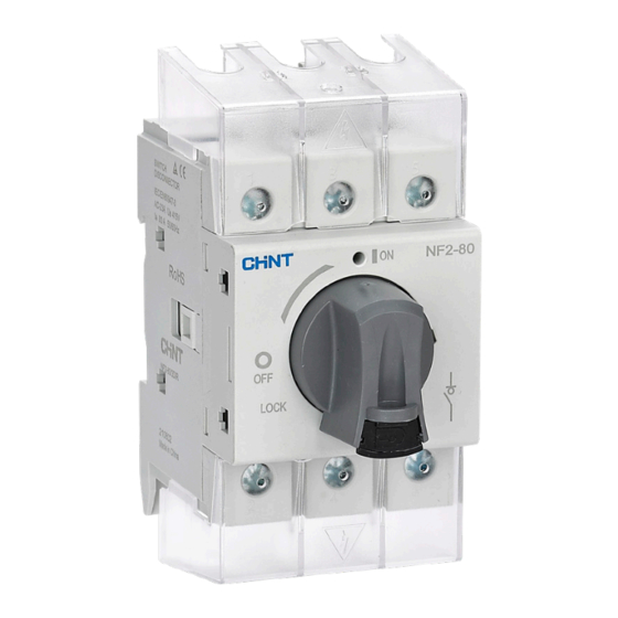
NF2
Load Switch
1.General
NF2 series load switch (hereinafter referred to as switch), mainly
used in electrical circuits with AC 50Hz or 60Hz, rated working
voltage up to 690V, and rated working current up to 125A,
It can be used to isolate faulty equipment or perform power
outage maintenance. It can be used as the main switch of
machine tools, fans, and pumps, and can also be used as the
start-stop switch of small-capacity motors.
Standards compliant:IEC/EN 60947-3,GB/T 14048.3
2. Type designation
2.1 Load switch model and its meaning
N F 2 -
Handle color:R,Grey handle with lock;RY,Red and
yellow knob;B,Black straight handle;BR,Black knob
(with lock)
Installation method:DI,Rail installation;H,Single hole
panel installation;HH,Mechanical combination;
DO,Door lock installation (extension rod);
BO,plastic box
series:3,3P
Conventional free air heating current
Design Number
Load Switch
Enterprise feature code
Note:4-pole products are realized by means of 3 poles + additional poles.
2.2 Additional pole model and its meaning
N F 2 -
Supporting installation form:Unmarked,DI/DO/BO;R,H
Additional pole type:PS,Sync disconnected;PD,Pre-
disconnect;PN,N terminal;PE,Ground wire
Product shell frame:40,40A and below;80,80A and
below;125,125A and below
Product number
2.3 Auxiliary pole model and its meaning
N F 2 -
Auxiliary pole:P1,1NO+1NC;P2,2NO
Product number
2.4 Terminal cover model and its meaning
N F 2 -
Number of poles:3,3 poles;1,1 pole
Additional pole type:TS,terminal cover
Product shell frame: 40, 40A and below; 80, 80A and
below; 125, 125A and below
Product number
092
P-
K
Advertisement
Table of Contents

Related Manuals for CHINT NF2 Series


Summary of Contents for CHINT NF2 Series
- Page 1 Fuses, Travel Switches, Universal Change-over Switches, Connection Terminals Load Switch 1.General NF2 series load switch (hereinafter referred to as switch), mainly used in electrical circuits with AC 50Hz or 60Hz, rated working voltage up to 690V, and rated working current up to 125A,...
- Page 2 fuses, Travel Switches, Universal Change-over Switches, Connection Terminals Load Switch 4. Technical data Table 1 Main technical parameters Model Frame grade NF2-40 NF2-80 NF2-125 Rated insulation voltage Ui (V) Rated impulse withstand voltage Uimp (kV) Conventional free air heating current Ith (A) Rated working current Ie (A, AC-23A) Rated short-time withstand current Icw,1s (kA) 1.26...
- Page 3 Load Switch Fuses, Travel Switches, Universal Change-over Switches, Connection Terminals 6.Overall and mouting dimensions The outline and installation dimensions of the switch are shown in following. See the box sticker for model specifications and weight. NF2-80/DI NF2-40/DI NF2-40/H NF2-125/DI NF2-125/H NF2-80/H NF2-80/TS NF2-40/TS...
- Page 4 fuses, Travel Switches, Universal Change-over Switches, Connection Terminals Load Switch NF2-40/HTS NF2-125/TS NF2-125/HTS NF2-80/HTS NF2-40/PN\PS\PD\PE NF2-80/PN\PS\PD\PE NF2-40/PNR\PSR\PDR\PER NF2-125/PN\PS\PD\PE...
- Page 5 Load Switch Fuses, Travel Switches, Universal Change-over Switches, Connection Terminals NF2-40/PNR\PSR\PDR\PER NF2-125/PNR\PSR\PDR\PER NF2-P1、P2 NF2-P1、P2 NF2-HH NF2-P1R、P2R NF2-40/BO NF2-80/BO...
- Page 6 fuses, Travel Switches, Universal Change-over Switches, Connection Terminals Load Switch NF2-125/BO 7. Order information 7.1 Check before installation 7.1.1 The technical data on the nameplate meets actual requirements. 7.1.2 Appearance:clean,intact parts, no loose fasteners. 7.1.3 Check the operating performance: perform 3 times of closing and opening operations, the product action is flexible and reliable;...
- Page 7 Load Switch Fuses, Travel Switches, Universal Change-over Switches, Connection Terminals 7.2.5 Additional auxiliary contact/additional fourth pole installation: as shown in Figure 30,31 Figure 30 Schematic diagram of accessory pole/auxiliary contact matching Figure 31 Schematic diagram of attachment pole installation 8.Maintenance and storage period 8.1 Daily maintenance Take appropriate measures to remove dust, water vapor, conductive dust and corrosive substances.
- Page 8 Load Switch Fuses, Travel Switches, Universal Change-over Switches, Connection Terminals 11.Accessories overview...
Need help?
Do you have a question about the NF2 Series and is the answer not in the manual?
Questions and answers