
Related Manuals for Pressure Tech LF-540 Series


Summary of Contents for Pressure Tech LF-540 Series
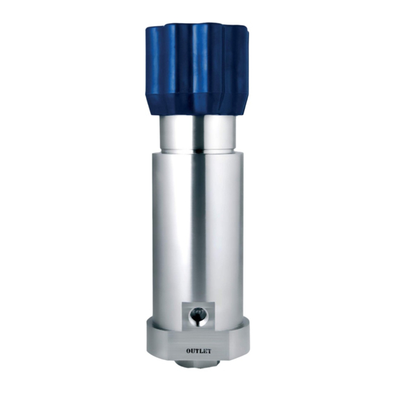
- Page 1 THE LF-540 SERIES Operating and Service Manual Series includes all variants of LF-540 Issue B July 2016...
-
Page 2: Table Of Contents
TABLE OF CONTENTS 1. Description ..........................3 2. Installation ..........................3 3. Operation ..........................3 4. Special Conditions for Safe Use ..................... 4 5. Hazardous Location Usage ..................... 4 6. Servicing and Maintenance ....................4 6.1. Servicing the LF-540 – Cv 0.2 Self Venting .............. 4 6.1.1. -
Page 3: Description
Filtration suited to the application is recommended upstream of the regulator. Should further assistance or information be required in relation to installation of any Pressure Tech regulator please contact the office, giving reference to the regulators part number and/or serial number. -
Page 4: Special Conditions For Safe Use
Self venting regulators can reduce the outlet pressure, by turning the hand wheel anti- clockwise, thereby venting the excess pressure through the vent port on the regulator. The vent on the LF540 exhausts to atmosphere. 4. Special Conditions for Safe Use Turning the hand wheel anti-clockwise (with pressure on the outlet) should be refrained on non-venting regulators. -
Page 5: Accessing The Main Valve Assembly
6.1.1. Accessing the Main Valve Assembly To access the Main Valve Assembly (MVA): Remove the securing M3 grub screw (26) from the regulator body (22). Unscrew the M3 button screw (27) and remove the name plate (4) from the hand wheel (5). -
Page 6: Reassembly - Sensor Assembly
6.1.3. Reassembly – Sensor Assembly Place the o-ring (25) into the sensor (14) and position to the lower face below the thread. Then, place the vent seat (13) into the sensor (14) with the o-ring groove facing downwards. iii. Place the respective o-ring (23, 24) and back up (1, 3) over the sensor holder (15) and sensor (14). -
Page 7: Reassembly - Regulator
6.1.4. Reassembly – Regulator Ensure that the sensor assembly has been correctly assembled as per 6.1.3 prior to following the instruction below. With the regulator body (22) upright and secured in a vice, place the main valve spring (16) and main valve (17) into the lower bore. Place the soft seat (18) into the bore, with the outer edge chamfer facing downwards. - Page 8 PT-550-006 SEAT NUT PT-540-A-LF BODY ‘A’ PORTING OR-0360-20 O’RING STD OR-0250-20 O’RING STD OR-0050-10 O’RING STD FIT-M3x4MM-SS-316-GRUBSCRW M3 GRUB SCREW FIT-M3-08-A4-70.0-SKT-BTN M3 BUTTON SCREW FILT-SCRM31040405-A 10MM SCREEN FILTER FIT-472011-SS-CIRCLIP 11MM CIRCLIP BEAR-51103-SS SS BEARING © Copyright of Pressure Tech Ltd...
-
Page 9: Technical Data
*Max Inlet Pressure determined by seat material and Cv of regulator. 8. Warranty Statement Pressure Tech Ltd guarantee all products correspond with their specification at the time of delivery and, with exception to wear and tear, wilful damage, negligence, and abnormal working conditions, will be free from defects for a period of 12 months from date of delivery.
Need help?
Do you have a question about the LF-540 Series and is the answer not in the manual?
Questions and answers