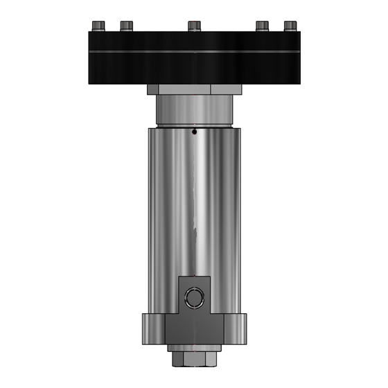
Summary of Contents for Pressure Tech LF-792 Series
- Page 1 THE LF-792 SERIES Operating and Service Manual Series includes all variants of LF-792 Issue B NOV 2019...
-
Page 2: Table Of Contents
TABLE OF CONTENTS 1. Description ......................... 3 2. Installation ......................... 3 3. Operation ........................4 4. Special Conditions for Safe Use ................. 5 5. Hazardous Location Usage ..................5 6. Servicing and Maintenance ..................5 6.1. Servicing Main Valve Assembly ................6 6.1.1. -
Page 3: Description
Filtration suited to the application is recommended upstream of the regulator. Should further assistance or information be required in relation to installation of any Pressure Tech regulator please contact the office, giving reference to the regulators part number and/or serial number. -
Page 4: Operation
‘Vent’ Port and should be vented downstream of the regulator. Ref Section 4. Important: The vent port should not be plugged or blocked at any time. The LF-792 series may be offered with pressure limiting, pressure locking or pre-set pressure options: Pressure limited regulators are fitted with locknuts on the adjusting mechanism in order to limit the maximum allowable downstream pressure. -
Page 5: Special Conditions For Safe Use
Any uncertainty should be clarified with Pressure Tech before working on the regulator. Pressure Tech Ltd recommends the use of Krytox GPL 205, as a lubricant for O-rings and Molykote 1000 paste for the adjusting screw, during servicing. -
Page 6: Servicing Main Valve Assembly
To ensure the best possible results from servicing, when re-assembling the regulator and any assemblies within it, ensure that all areas of the components and the regulator body are cleaned and free from contaminants which may result in failure of the regulator. -
Page 7: Accessing The Sensing Assembly (Sa) - Dome Top
6.1.2. Accessing the Sensing Assembly (SA) – Dome Top The loading mechanism and vent seat for the LF-792 can be accessed from the top of the regulator. Ensure the spring is de-compressed by rotating the hand wheel fully anti-clockwise and follow the instructions below: *Note: Figure 1 should be used as a reference for the following set of instructions Remove the securing grub screw (3) from the regulator body (17). - Page 8 xix. Place the lower spring rest (32) with 32mm x 2mm ‘O’ ring (7), onto the load spring (20) within the bonnet (19). Screw the top works onto the regulator body and using a torque wrench or equivalent with 47mm open end, tighten to 120Nm. xxi.
- Page 9 BAFFLE PLATE PT-C-088-013 MAIN VALVE PT-C-089-008 SEAT HOLDER PT-C-091 VENT SEAT NUT PT-C-093-002 SENSOR HOLDER 9mm PT-C-094-002 9mm SENSOR PT-C-095-001 SPRING REST - DOME PT-C-099 MAIN VALVE SPRING PT-C-132 LOCK NUT PT-C-249 TECASINT SEAT © Copyright of Pressure Tech Ltd...
-
Page 10: Accessing The Balanced Main Valve Assembly (Mva)
6.2.1. Accessing the Balanced Main Valve Assembly (MVA) *Note: Figure 2 should be used as a reference for the following set of instructions To access the Main Valve Assembly: Firmly clamp the flats at the bottom of the regulator in the vice, with the bottom nut (18) facing up. -
Page 11: Accessing A Threaded Sensing Assembly (Sa) - Threaded
6.2.2. Accessing a Threaded Sensing Assembly (SA) - Threaded The loading mechanism and vent seat for the LF-792 can be accessed from the top of the regulator. Ensure the spring is de-compressed by rotating the hand wheel fully anti-clockwise and follow the instructions below: *Note: Figure 2 should be used as a reference for the following set of instructions Remove the securing grub screw (3) from the regulator body (22). - Page 12 LARGE NYLON HAND WHEEL PT-C-049 NAMEPLATE PT-C-085 SENSOR HOLDER PT-C-086 BAFFLE PLATE PT-C-087 12mm SENSOR PT-C-088-010 BALANCED MAIN VALVE CV 0.3 PT-C-089-XXX SEAT HOLDER PT-C-091 VENT SEAT NUT PT-C-132 LOCK NUT PT-C-251 TECASINT SEAT - BALANCED © Copyright of Pressure Tech Ltd...
- Page 13 6.3.1. Accessing the Air Actuator Bonnet Assembly – Threaded The Air Actuated bonnet mechanism for the LF-792 can be accessed from the top of the regulator. Ensure the air supply to the Actuator Bonnet is fully depleted, before carrying and following instructions below: *Note: Figure 3 should be used as a reference for the following set of instructions Remove the securing grub screw (2) from the regulator body (26), using a 2mm Allen...
- Page 14 6.3.2 Figure 3 – Section view of the LF-792 – Air Actuator Bonnet/Threaded SA/Balanced MVA PARTS LIST ITEM PART NUMBER DESCRIPTION BUSH-1525DU GLACIER DU BUSH FIT-M3x6MM-SS-316-GRUBSCRW M3 X 6mm GRUB SCREW FIT-M5-25-A4-70.0-SKT-CAP M5 x 20mm CAP SCREW FIT-M5-SS-A4-SPR-WASHER SPRING WASHER FIT-M6-16-A4-70.0-SKT-CSK M6 x 16mm SS316 COUNTERSUNK SCREW FIT-M6-20-A4-70.0-SKT-CAP...
-
Page 15: Technical Data
Gas: Bubble tight (ANSI/FCI 70-2) 8. Warranty Statement Pressure Tech Ltd guarantee all products correspond with their specification at the time of delivery and with exception to wear and tear, wilful damage, negligence, and abnormal working conditions, will be free from defects for a period of 12 months from date of delivery.


Need help?
Do you have a question about the LF-792 Series and is the answer not in the manual?
Questions and answers