
Related Manuals for Pressure Tech LF-690


Summary of Contents for Pressure Tech LF-690
- Page 1 THE LF-690/691 SERIES Operating and Service Manual Series includes all variants of LF-690/691 Issue D March 2020...
-
Page 2: Table Of Contents
6.1.1. Accessing the Unbalanced Main Valve Assembly (MVA) ........6 6.1.2. Accessing the Domed Sensor Assembly (SA) ............7 6.1.3. Figure 1 – Sectional View of the LF-690 (with Domed SA/Unbalanced MVA) ..8 6.2. Servicing the LF-690 Balanced Regulator ............... 9 6.2.1. -
Page 3: Description
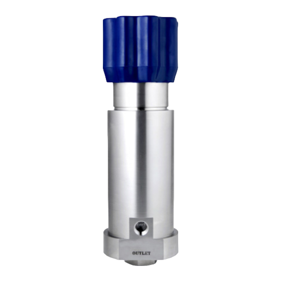
1. Description The LF-690 is a single stage piston sensed pressure regulator, capable of a maximum 690 bar inlet pressure. This can then be controlled to a range of outlet pressures depending upon the sensing arrangement. As standard, the LF-690 comes with a Tungsten Carbide main valve and heat treated 17-4ph seat, which provides excellent resistance to erosion on hydraulic media. -
Page 4: Operation
The LF-690 incorporates a segregated captured vent, which allows the outlet pressure to be reduced whilst turning the hand wheel anti-clockwise. Excess pressure is vented off through the ‘Vent’... -
Page 5: Special Conditions For Safe Use
99/92/EC. 6. Servicing and Maintenance With so many variants of the LF-690 available, the following section uses three examples with the aim of covering most options. The product supplied may vary from these examples. -
Page 6: Servicing The Lf-690 Regulator
6.1. Servicing the LF-690 regulator *Note: Fig 1 should be used as a reference for the following set of instructions 6.1.1. Accessing the Unbalanced Main Valve Assembly (MVA) To access the Main Valve Assembly: Firmly clamp the flats at the bottom of the regulator in the vice, with the bottom nut (7) facing up. -
Page 7: Accessing The Domed Sensor Assembly (Sa)
6.1.2. Accessing the Domed Sensor Assembly (SA) The loading mechanism and vent seat for the LF-690 can be accessed from the top of the regulator. Ensure the spring is de-compressed by rotating the hand wheel fully anti- clockwise and follow the instructions below: Remove the securing grub screw (20) from the regulator body (1). - Page 8 6.1.3. Figure 1 – Sectional View of the LF-690 (with Domed SA/Unbalanced MVA) Parts List Item Part Number Description PT-690-N-LF BODY - N PORTING PT-C-029-007 CERAMIC SEAT PT-C-086 BAFFLE PLATE PT-C-088-006-002 MAIN VALVE PT-C-089-008 SEAT CARTRIDGE PT-C-099 MV SPRING PT-690-010...
-
Page 9: Servicing The Lf-690 Balanced Regulator
6.2. Servicing the LF-690 Balanced Regulator *Note: Fig 2 and 3 should be used as a reference for the following set of instructions 6.2.1. Accessing the Balanced Main Valve Assembly (MVA) To access the Main Valve Assembly: Disassembly Firmly clamp the flats at the bottom of the regulator Body (1) in a vice, with the bottom nut (3) facing up. - Page 10 6.2.2. Figure 2 – Sectional View of the LF-690 Balanced MVA...
-
Page 11: Accessing The Threaded Sensor Assembly
6.2.3. Accessing the Threaded Sensor Assembly The loading mechanism and vent seat for the LF-690 can be accessed from the top of the regulator. Ensure the spring is de-compressed by rotating the hand wheel fully anti-clockwise and follow the instructions below: Remove the securing grub screw (26) from the regulator body (1). - Page 12 6.2.4. Figure 3 – Sectional View of the LF-690 (with Threaded SA/Balanced MVA) Parts List Item Part Number Description PT-690-N-LF-03A-002 BODY - N PORTING PT-690-004 MAIN VALVE SPRING PT-690-010-001 BOTTOM BODY NUT PT-690-011-013 CONNECTOR PIN PT-690-020 WASHER PT-690-041 PTFE SPACER...
-
Page 13: Servicing The Lf-691 Regulator
6.3. Servicing the LF-691 regulator *Note: Fig 4 should be used as a reference for the following set of instructions 6.3.1. Accessing the Main Valve Assembly To access the Main Valve Assembly: Firmly clamp the flats at the bottom of the regulator in the vice, with the bottom nut (7) facing Remove the bottom nut (7) from the body (1). -
Page 14: Accessing The Sensor Assembly
6.3.2. Accessing the Sensor Assembly The loading mechanism and vent seat for the LF-691 can be accessed from the top of the regulator. Ensure the spring is de-compressed by rotating the T-Bar fully anti-clockwise and follow the instructions below: Remove the T-Bar (32, 33) by unscrewing one side whilst firmly gripping the other. With the regulator secured up-right in a vice, remove the bonnet (31) by using a torque wrench or equivalent with 47mm open end. - Page 15 O' RING STD OR-BS806 O' RING STD OR-0350-20 O' RING STD ORB-PT-C-168 PTFE BACK UP RING ORB-PT-C-167 PTFE BACK UP RING ORB-PT-C-166 PTFE BACK UP RING PT-C-040-008 BONNET PT-C-180 T BAR HANDLE PT-C-107 T BAR HANDLE © Copyright of Pressure Tech Ltd...
-
Page 16: Technical Data
Gas: Bubble tight 8. Warranty Statement Pressure Tech Ltd guarantee all products correspond with their specification at the time of delivery and, with exception to wear and tear, wilful damage, negligence, and abnormal working conditions, will be free from defects for a period of 12 months from date of delivery.
Need help?
Do you have a question about the LF-690 and is the answer not in the manual?
Questions and answers