Table of Contents
Advertisement
Operator Manual
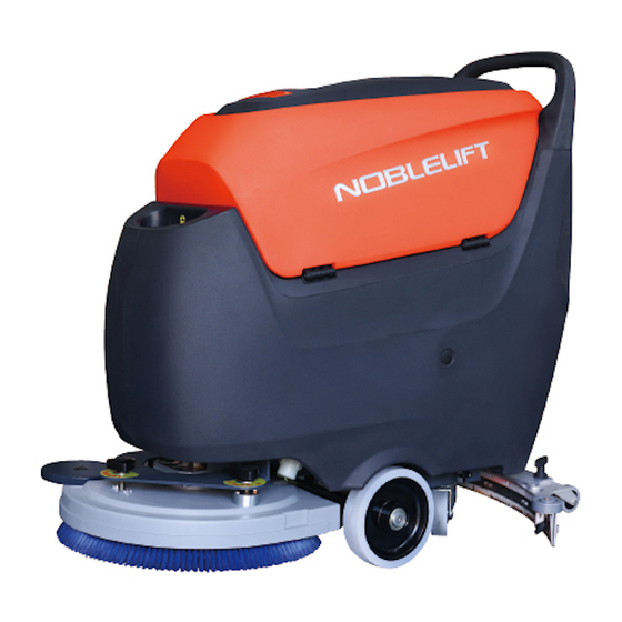
NB530 Walk-Behind Floor Scrubber
WARNING
Do not operate the floor scrubber before
reading and understanding the operator
manual.
NOTE:
• Please check product type and parameters of
your scrubber in this manual as well as on the
ID-plate.
• Keep this operator manual for future reference.
Version 05/2021
NB530-SMS-001-EN
Advertisement
Table of Contents
Troubleshooting

Related Manuals for Noblelift NB530


Summary of Contents for Noblelift NB530
- Page 1 Operator Manual NB530 Walk-Behind Floor Scrubber WARNING Do not operate the floor scrubber before reading and understanding the operator manual. NOTE: • Please check product type and parameters of your scrubber in this manual as well as on the ID-plate.
-
Page 2: Table Of Contents
CONTENTS INTRODUCTION ..........................1 MANUAL PURPOSE AND CONTENT ...................1 HOW TO KEEP THE MANUAL ....................1 DECLARATION OF CONFORMITY ..................1 ACCESSORIES AND MAINTENANCE ..................1 CHANGE AND IMPROVEMENT ....................2 INTENDED USE ........................2 MACHINE IDENTIFICATION ....................2 TRANSPORTING AND UNCRATING ..................2 SAFETY ............................3 SAFETY SYMBOLS .........................3 GENERAL SAFETY INSTRUCTIONS ...................3 MACHINE SETUP..........................6 MAIN COMPONENTS ......................6... -
Page 3: Introduction
INTRODUCTION NOTE The code of related components in ( ) can be found in the chapter of machine description. MANUAL PURPOSE AND CONTENT ⚫ This manual is to provide the operator with the necessary information for the correct and safe use of the machine, which includes the technical data, safety, operation, storage, maintenance, accessories and dispose of the machine. -
Page 4: Change And Improvement
CHANGE AND IMPROVEMENT ⚫ Our company is committed to the continuous improvement of the products and reserves the right to notify the improvements and changes of the products that have been sold. INTENDED USE ⚫ This floor scrubber can be used in commercial and industrial environments, and it is suitable for cleaning smooth and hard floors (washing and sewage collecting). -
Page 5: Safety
SAFETY The following symbols indicate potential dangers. In any case, please read this information carefully and take necessary precautions to avoid possible injury and property loss. It is necessary to have cooperation of the operator to avoid injury, otherwise any precautions are ineffective. Most of the safety accidents that occur in factories are caused by people who fail to obey simple and effective instructions during working and walking. - Page 6 ⚫ Do not work on the ground that cannot bear the weight of the machine. ⚫ Do not use the machine near toxic, dangerous, flammable, explosive dust, liquid, or steam. ⚫ The battery will produce explosive hydrogen during the charging process. Please keep the recovery tank open during charging, and ensure that the surrounding area is well ventilated and away from open flames.
- Page 7 ⚫ Do not remove or change the stickers on the machine. ⚫ The vibration generated by the machine when operating in accordance with the instructions is safe. The vibration of the machine should be lower than 2.5m/s² (98/37/EEC-EN 1033/1995). ⚫ This machine cannot be used on roads or public streets.
-
Page 8: Machine Setup
MACHINE SETUP MAIN COMPONENTS 1. Control panel 2. Handle 3. Recovery tank lid 4. Recovery tank 5. Hinge 6. Solution tank 7. Brush disk cover 8. Brush disk/ Pad driver 9. Load wheel 10. Solution tank level hose 11. Caster 12. - Page 9 28. Battery 29. Identification plate 30. Tank rope 31. Vacuum pressure plate 32. Balance adjusting knob 33. Brush angle adjusting knob 34. Battery indicator/ fault code display 35. Vacuum motor button indicator 36. Vacuum motor button 37. Brush/pad driver indicator 38.
-
Page 10: Main Components Description
MAIN COMPONENTS DESCRIPTION Control panel (1) --This panel is the control part of the machine, see the description of control and switch. Handle (2) -- Hold this handle and operate the machine through it. Recovery tank lid (3) -- This lid seals the recovery tank. When cleaning the recovery tank, it can be taken off and hanged on the fill-port. -
Page 11: Technical Data
Solution flow indicator (42) -- The three indicator lights indicate three different solution flows. Solution flow button (43) -- This button is used for adjusting the flow of detergent/water supplied to the brush. Three flows are available. TECHNICAL DATA Model NB530 Machine Height 1060 Solution tank capacity Recovery tank capacity... -
Page 12: Electrical Wiring Diagram
ELECTRICAL WIRING DIAGRAM Brush Motor Vacuum motor indicator Vacuum Motor Water flow 2 Fuse 50A Water flow 3 Current limit 40A Water flow 1 Current limit 40A Brush removing switch Water flow control EM valve Brush motor switch Key switch Water flow switch Vacuum motor switch Brush motor indicator... -
Page 13: Installing And Removing Disk Brushes/Pads
1. Open the recovery tank lid (3) to check whether the recovery tank is empty, if not, drain it through the drain hose (12). 2. Remove the recovery tank lid (3), hang it on the solution tank fill-port (22), and then turn the recovery tank (4) to one side. -
Page 14: Draining Tanks
5. Press the pedal (17) to place the brush disk/pad driver on the ground. 6. Press the brush disk/pad driver button (38) and vacuum motor button (36), the brush disk/pad driver indicator light (37) and vacuum motor indicator light (35) will be on. 7. -
Page 15: After Use
A sudden noise increase of the vacuum motor indicates the recovery tank (4) needs to be drained immediately. CAUTION ! If the vacuum path is closed accidentally (for example, when the float ball is activated because of a sudden machine movement), to resume the operation: turn off the vacuum motor by pressing the vacuum motor button(36), then open the recovery tank lid (22) and check if the float ball inside the shut-off screen (20) has gone down to the water level. -
Page 16: Regular Maintenance Checklist
maintenance. The following checklist provides a general maintenance schedule for the machine. The maintenance interval depends on the working condition of the machine, which should be set by the person in charge of maintenance. WARNING ! The procedures must be carried out with the machine off and the battery disconnected. Moreover, read carefully the instructions in the Safety chapter before performing any maintenance procedures. -
Page 17: Cleaning Squeegee
Connect the charger to the charging socket (19) of the machine. Connect the charger to the power supply and start charging. When the charger shows fully charged, remove the charger from the power supply and the charging socket in turn. CAUTION!... -
Page 18: Cleaning Brush/Pad
CLEANING BRUSH/PAD CAUTION! It is advisable to wear protective gloves when cleaning the brush/pad because there may be sharp debris. 1. Remove the brush disk/ pad driver from the machine according to the methods described above. 2. Clean the brush disk/ pad driver with water and detergent. 3. -
Page 19: Solution Filter Cleaning
SOLUTION FILTER CLEANING 1. Close the solution tank water tap (27). 2. Remove the filter cover and the filter screen, clean them with water, and then fit them back. 3. Fix the filter cover. NOTE The filter screen (E) must be correctly fitted on the housing (G). 4. -
Page 20: Common Trouble Shooting
COMMON TROUBLE SHOOTING Trouble Possible Cause Remedy The recovery tank is full. Drain the tank. The hose is disconnected from the Connect the hose and the squeegee. squeegee. Clean the float shut-off screen and The float shut-off screen is clogged. check the float. -
Page 21: Scrapping And Dispose
SCRAPPING AND DISPOSE Have the machine scrapped by a qualified scrapper. Before scrapping the machine, remove and separate the following materials, which must be properly disposed of according to relevant laws and regulations: – Battery – Brush disk/pad driver – Plastic hoses and components –...
Need help?
Do you have a question about the NB530 and is the answer not in the manual?
Questions and answers